
In database management, logical database design is the crucial bridge that turns abstract business ideas into a structured, real-world data system. Whether you call it logical data modeling, database schema design, or relational schema mapping, this process focuses entirely on organizing your data efficiently and defining relationships clearly without getting bogged down by specific software, storage, or physical hardware constraints.
In this tutorial, we will learn what logical database design involves, why it is essential for avoiding costly data errors, and how to step-by-step convert an Entity-Relationship (ER) model into a fully functional relational schema.
What is logical database design?
Logical database design is the process of translating high-level business requirements into a clear blueprint for organizing data, without worrying about the specific software or hardware that will store it.
It focuses on ensuring data is organized efficiently, accurately, and without unnecessary duplicates, creating a structured plan that can later be built in any database system, like MySQL or Oracle.
What does it involve?
Logical database design involves taking real-world business requirements and organizing them into a clear, detailed blueprint for how data will be structured.
It involves converting an Entity-Relationship (ER) diagram into a relational model, translating entities into tables, attributes into columns, and relationships into primary and foreign keys and is one of the central steps of logical database design.
It also includes refining the structure through a process called normalization to eliminate repetitive data and prevent mistakes, resulting in a clean, logical map that can be turned into a real database using any system you choose.
Why is it needed?
Without this phase, databases are prone to serious flaws, such as storing duplicate information across multiple places, which wastes storage space and creates inconsistencies (for example, updating a customer’s address in one table but forgetting to update it in another).
It provides a clear, software-independent structure that ensures all business rules are captured accurately, speeds up future data retrieval, and prevents the extremely expensive work of having to redesign and rebuild a poorly planned database after it is already live.
Steps in converting ER model to relational model
Following are the steps involved in converting an ER model to relational model:
- Map strong entity types to tables: Create a standalone table for every regular (strong) entity in the ER diagram. The attributes of the entity become the columns of the table, and the entity’s key attribute is chosen as the table’s primary key.
- Map weak entity types to tables: Create a table for every weak entity. Include all of its simple attributes as columns, and form its composite primary key by combining its partial key with the primary key of its identifying (owner) entity.
- Map 1:1 binary relationships: Choose one of the two participating entity tables and add the primary key of the other table as a foreign key inside it. If one side of the relationship is mandatory (total participation), place the foreign key on that side to avoid empty (null) values.
- Map 1:N binary relationships: Identify the entity on the “many” side of the relationship and insert the primary key of the “one” side table into it as a foreign key. This connects each record on the “many” side directly to its single parent record.
- Map M:N binary relationships: Create a brand-new table (often called a junction or bridge table) specifically for the relationship. Include the primary keys from both participating entities as foreign keys in this new table, and combine them to form its composite primary key. Any attributes attached to the relationship itself also become columns in this table.
- Map multivalued attributes: Create a separate table for any attribute that can hold multiple values for a single entity instance. Include the attribute value itself alongside the primary key of the parent entity (which acts as a foreign key). The combination of both fields forms the primary key of this new table.
- Map n-ary relationships (relationships involving 3+ entities): Create a new table dedicated to the higher-degree relationship. Include the primary keys from all participating entities as foreign keys inside this table, and add any attributes belonging to the relationship as extra columns.
University database example
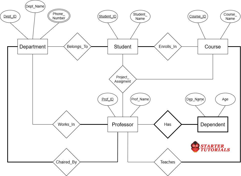
To understand the process of converting an ER diagram to relational model (tables), let’s consider a university database as an example. Consider the following ER diagram for our university database:
Now, let’s see an example for every step of converting an ER diagram to relational model:
Map strong entity types to tables
Create a table for each regular entity (strong entity), assigning its primary key (PK). So, the tables are:
- Department (Dept_ID (PK), Dept_Name)
- Student (Student_ID (PK), Student_Name)
- Professor (Prof_ID (PK), Prof_Name)
- Course (Course_ID (PK), Course_Name)
Map weak entity types to tables
Dependent is a weak entity dependent on Professor. It stores details about a professor’s family members or dependents (such as a spouse or child) for benefits or emergency contact purposes.
Combine the partial key Dep_Name with the foreign key Prof_ID from Professor to form the composite primary key. So, we get a new table:
- Dependent (Prof_ID, Dep_Name, Age)
In the above table, (Prof_ID + Dep_Name) is a PK and Prof_ID is a foreign key (FK). Prof_ID references Professor (Prof_ID).
Map 1:1 binary relationships
For the Department Chaired_By Professor relationship, place the primary key of Professor as a foreign key inside Department (mandatory side). So the updated Department table is:
- Department (Dept_ID, Dept_Name, Chair_Prof_ID)
In the above table, Chair_Prof_ID references Professor(Prof_ID). So, Chair_Prof_ID is a FK.
Map 1:N binary relationships
Place the primary key of the “1” side as a foreign key (FK) inside the “N” (many) side table.
Student Belongs_To Department (1:N): Put Dept_ID in Student. So, the updated Student table is:
- Student (Student_ID, Student_Name, Dept_ID)
In the above table, Dept_ID references Department(Dept_ID). So, Dept_ID is a FK.
Professor Works_In Department (1:N): Put Dept_ID in Professor. So, the updated Professor table is:
- Professor (Prof_ID, Prof_Name, Dept_ID)
In the above table, Dept_ID references Department(Dept_ID). So, Dept_ID is a FK.
Professor Teaches Course (1:N): Put Prof_ID in Course. So, the updated Course table is:
- Course (Course_ID, Course_Name, Prof_ID)
In the above table, Prof_ID references Professor(Prof_ID). So, Prof_ID is a FK.
Map M:N binary relationships
For Student Enrolls_In Course, create a junction table containing the primary keys from both entities as foreign keys. Together, they form the composite primary key. So, we get a new table called Enrollment as:
- Enrollment (Student_ID, Course_ID)
In the above table, (Student_ID + Course_ID) is the PK. Also, Student_ID references Student(Student_ID) and Course_ID references Course(Course_ID). So, Student_ID and Course_ID are FKs.
Map multivalued attributes
As Phone_Number is a multi-valued attribute, create a separate table as:
- Department_Phone (Dept_ID, Phone_Number)
In the above table, Dept_ID is the PK. Also, Dept_ID references Department(Dept_ID). So, Dept_ID is also a FK.
Map n-ary relationships
The n-ary relationship, such as a 3-way assignment connecting Student, Course, and Professor tables (for project evaluation/mentorship) must have a new table as:
- Project_Assignment (Student_ID, Course_ID, Prof_ID)
In the above table, (Student_ID + Course_ID + Prof_ID) is the PK. Also, Student_ID references Student(Student_ID), Course_ID references Course(Course_ID) and Prof_ID references Professor(Prof_ID). So, Student_ID, Course_ID and Prof_ID are FKs.
Finally, after converting our ER diagram into relational model, we get the database schema as:
Department (Dept_ID, Dept_Name, Chair_Prof_ID)

Department_Phone (Dept_ID, Phone_Number)

Professor (Prof_ID, Prof_Name, Dept_ID)

Dependent (Prof_ID, Dep_Name, Age)

Student (Student_ID, Student_Name, Dept_ID)

Course (Course_ID, Course_Name, Prof_ID)

Enrollment (Student_ID, Course_ID)

Project_Assignment (Student_ID, Course_ID, Prof_ID)
Logical database design also involves normalization, which will be covered in another article.

Mr. P.S.Suryateja, also known as Suryateja Pericherla, is at present a Research Scholar (full-time Ph.D.) in the Dept. of Computer Science & Systems Engineering at Andhra University, Visakhapatnam. Previously worked as an Associate Professor in the Dept. of CSE at Vishnu Institute of Technology, India.
He has 14+ years of teaching experience and is an individual researcher whose research interests are Cloud Computing, Internet of Things, Computer Security, Network Security and Blockchain.
He is a member of professional societies like IEEE, ACM, CSI and ISCA. He published several research papers which are indexed by SCIE, WoS, Scopus, Springer and others.
Leave a Reply