
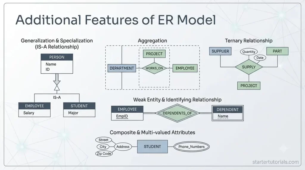
While standard Entity-Relationship diagrams cover the basics of database design, real-world data requirements often demand more nuanced controls. Understanding the additional features of ER model systems helps you capture complex business rules directly within your conceptual schema.
Need for additional features
Standard Entity-Relationship (ER) models use basic building blocks like simple entities, attributes, and relationships to sketch out a database. However, real-world data and business rules are complex. Standard ER models are often too basic to capture those real-life restrictions and relationships accurately.
The additional features exist to bridge the gap between simple diagrams and real-world complexity, ensuring your database design reflects true business logic without data errors or redundancy.
List of additional features in ER model
The additional features of ER model that helps to capture more of the semantics are:
- Key constraints
- Participation constraints
- Weak entities
- Class hierarchies
- Aggregation
Let’s understand about each additional feature of ER model in detail.
Key constraints
- The Need: Real life requires uniquely identifying every single item. Without a key constraint, a database could accidentally allow two employees to share the exact same Social Security Number or Employee ID. In terms of a relationship, a key constraint enforces that at most one instance of an entity is linked one or more instances of another entity.
- What it Solves: It enforces uniqueness, ensuring that every record in an entity set can be distinguished from every other record.
- Notation:
- Primary Key: The attribute name inside an oval is underlined (e.g., Emp_ID).
- Candidate Key / Alternate Key: Drawn as normal ovals linked to the entity, or specified alongside table schemas.
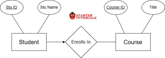
- Relationship: A key constraint with respect to a relationship is represented as an arrow, where the arrow head points towards the entity that must have at most one instance participating in the relationship.
For example, consider the Enrolls In relationship between the Student and Course entities. Based the requirements let’s say we have to represent a rule that a student is required to enroll in at most one course. Such key constraint can be represented in an ER diagram as shown in the image below:
Participation constraints
- The Need: Not all real-world relationships are optional. For instance, a company might have a rule that an Employee can belong to a department, but every Department must have a manager.
- What it Solves: It defines whether every entity in a set must participate in a relationship (Total Participation) or if it is optional (Partial Participation), preventing orphan or incomplete data.
- Notation:
- Total Participation (Mandatory): Drawn using a double line or a solid line connecting the entity rectangle to the relationship diamond.
- Partial Participation (Optional): Drawn using a single line connecting the entity rectangle to the relationship diamond.
For example, consider the Enrolls In relationship between the Student and Course entities. Based the requirements let’s say we have to represent a rule that a student must enroll in at least one course, but there can be a course which is not taken by any student. Such participation constraints can be represented in an ER diagram as shown in the image below:
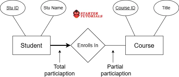
In the above image, Student entity is having total participation and Course entity is having partial participation in the relationship.
Weak entities
Weak Entities (Dependent Objects)
- The Need: Some items cannot exist in the real world on their own. For example, a “Dependent” (a child on an employee’s health plan) only exists in the company system because of the “Employee.” If the employee leaves, the dependent data shouldn’t exist independently.
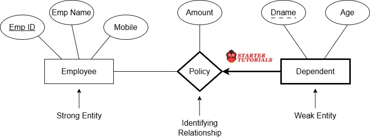
- What it Solves: It allows the database to represent entities that don’t have their own unique key and rely entirely on a primary “owner” entity for their identity. Entity which does not have a unique key is called a weak entity. The owner entity on which a weak entity depends is called a strong or primary entity. The relationship between the weak and strong entities is called an identifying relationship. The weak entity must have total participation in the identifying relationship set.
- Notation:
- Weak Entity: Drawn as a double-outlined or solid rectangle.
- Identifying Relationship: Drawn as a double-outlined or solid diamond.
- Partial Key (Discriminator): Drawn as a dashed underline inside an oval.
For example, consider an employee in a company. The employee can have a health policy, which will have the family members as dependents. These dependents exist in the database only in the context of the policy. A dependent might not have any unique key. So, a dependent is a weak entity. To identity a dependent uniquely, it relies on the employee entity. In this context, Dependent is the weak entity and Employee is the strong entity. Policy is the identifying relationship. These elements are represented in an ER diagram as shown in the image below:
Class hierarchies
- The Need: Real-world entities often share common traits but have unique differences. For example, both Hourly Employee and Salaried Employee are types of Employee. They share an ID and Name, but only hourly employees have an Hourly Rate.
- What it Solves: It introduces “IS-A” relationships (specialization and generalization), allowing to group common attributes at a higher level to eliminate redundant data while catering to specific sub-types.
- Notation:
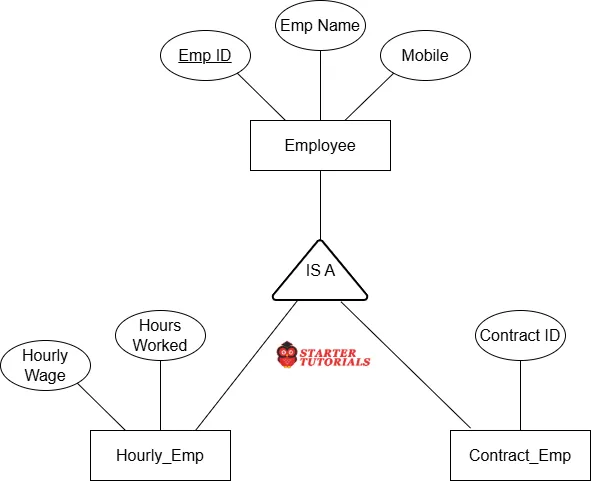
- A triangle labeled “IS-A” placed between a superclass (parent) entity and its subclass (child) entities.
For example the IS-A relationship between the Employee super entity and Hourly_Emp & Contract_Emp sub entities can be represented in an ER diagram as shown in the image below:
Aggregation
Aggregation (Relationships Among Relationships)
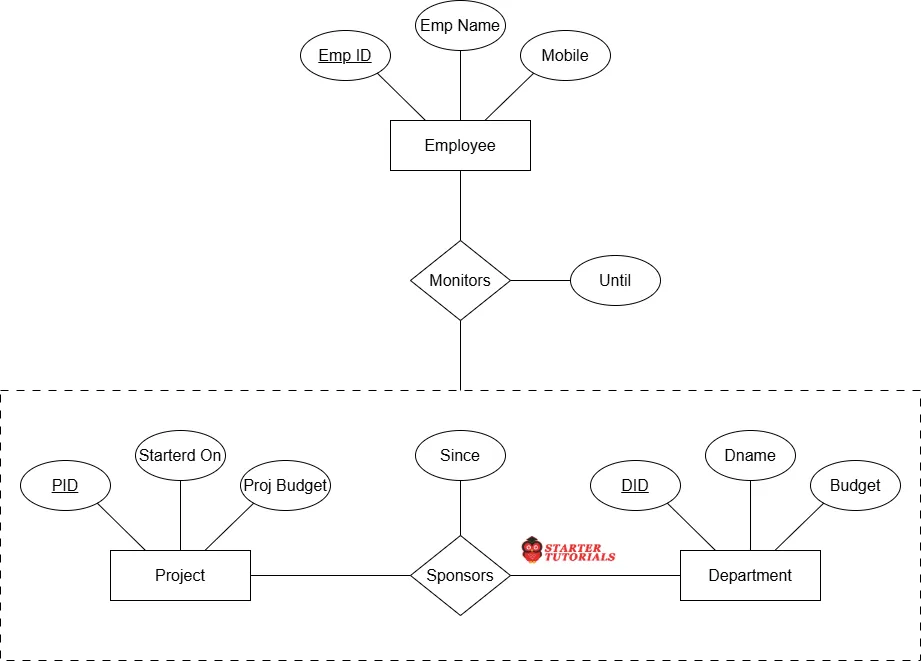
- The Need: Basic ER models only allow relationships directly between entities. But sometimes, a relationship itself needs to participate in another relationship. For example, a Department sponsors a Project, and that whole combination (Department + Project) needs to be assigned to a specific Employee to be managed by him/her.
- What it Solves: It treats an entire relationship between two entities as a single higher-level entity, so you can attach further relationships to it without creating messy, multi-way redundancy.
- Notation:
- Draw a dashed or solid rectangular box around an entire relationship (including its participating entities), treating that whole group as a single higher-level entity connected to another relationship diamond.
An example of an aggregation in an ER diagram is shown in the image below:

Mr. P.S.Suryateja, also known as Suryateja Pericherla, is at present a Research Scholar (full-time Ph.D.) in the Dept. of Computer Science & Systems Engineering at Andhra University, Visakhapatnam. Previously worked as an Associate Professor in the Dept. of CSE at Vishnu Institute of Technology, India.
He has 14+ years of teaching experience and is an individual researcher whose research interests are Cloud Computing, Internet of Things, Computer Security, Network Security and Blockchain.
He is a member of professional societies like IEEE, ACM, CSI and ISCA. He published several research papers which are indexed by SCIE, WoS, Scopus, Springer and others.
Leave a Reply