
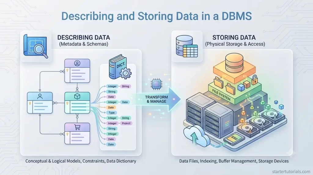
When building modern software applications, one of the most fundamental tasks is describing and storing data in a DBMS. Before writing a single SQL query or creating physical storage files, developers must define how information is structured, related, and managed. A database management system handles these complex mechanics behind the scenes, allowing you to organize raw data into a coherent, high-level blueprint known as a data model. In this tutorial, we will explore how DBMS data modeling bridges the gap between real-world business requirements and structured database storage, taking you step-by-step from conceptual design to tables, rows, and columns.
A DBMS allows a user to define the data to be stored in terms of a data model. Think of a data model as a blueprint or map of your data.
What is a data model?
A data model is a collection of high-level data description that hide many low-level storage details.
When you use a system (like a phone app or a website), you only care about what information is there, not how the computer’s hard drive physically stores bits, bytes, or files. The data model acts as a bridge: it organizes information into clear concepts while hiding all the complicated underlying mechanics.
A Data Model is the broad, umbrella concept. It refers to any abstract framework used to describe data, its relationships, constraints, and semantics. It is not a single specific technology or tool. It is the general idea of modeling data.
We can divide a data model into two parts. They are:
- Semantic data model
- Logical data model
Semantic data model
The semantic data model is used at the Conceptual Level of database design to capture real-world business requirements visually without worrying about technical implementation details. The Entity-Relationship (ER) Model is a specific Semantic Data Model.
- Focus: Real-world entities, attributes, and relationships.
- Format: Visual diagrams (rectangles, ovals, diamonds).
- Role in Lifecycle: Step 1 in designing a database (the whiteboard phase).
Logical data model
The logical data model structures data into a specific structure, for example, as mathematical relations (tables) with rows and columns. The Relational Model is a specific Logical Data Model (introduced by E.F. Codd).
- Focus: Tables, primary keys, foreign keys, constraints, and normalization.
- Format: Structured tables and SQL schema.
- Role in Lifecycle: Step 2 in designing a database (converting the ER diagram into actual code/tables).
How does the semantic data model (ER model) and the logical data model (relational data model) work together?
In real-world software engineering, we use these concepts sequentially. Let’s consider a university database as an example.
- Category: You are tasked with creating a Data Model for a university.
- Design (ER Model): You draw an ER Model showing Student and Course entities connected by an Enrolls_In relationship so stakeholders can review the business logic.
- Implementation (Relational Model): You translate that ER diagram into a Relational Model by creating STUDENT, COURSE, and ENROLLMENT tables with Primary and Foreign Keys, ready to be created using SQL inside a DBMS.
Comparison of data model, semantic model and logical model
The following table provides a quick comparison of the data model, semantic model and logical model.
| Aspect | Data Model | ER Model (semantic model) | Relational Model (logical model) |
|---|---|---|---|
| What is it? | General concept/category | A specific conceptual design model | A specific logical implementation model |
| Abstraction Level | Any | High (Conceptual / Blueprint) | Medium (Logical / Schema) |
| Primary Unit | N/A | Entities & Relationships | Tables (Relations) & Keys |
| Main Audience | System Architects | Business Analysts & Stakeholders | Database Administrators & Developers |
| Handling Relationships | N/A | Represented visually using Diamonds | Represented using Foreign Keys |
Data modeling case study
To understand the difference, think of the Semantic Data Model (ER model) as the conceptual, real-world visual plan, and the Relational Data Model (logical model) as the structured implementation inside the database using tables.
Here is how the same university information looks in both models.
Semantic data model of a university
A Semantic (ER) Model captures the meaning and relationships of real-world objects using visual components (Entities, Attributes, and Relationships). It reads almost like a diagram of real-world business rules.
Visual Components:
- Entities (Rectangles): Real-world objects (e.g., STUDENT, COURSE).
- Attributes (Ovals): Properties of an entity (e.g., StudentID, Name, Credits).
- Relationships (Diamonds): How entities interact (e.g., Enrolls_In).
Example ER Conceptual Description:
- Entity: STUDENT with attributes StudentID (Key), Name, Email.
- Entity: COURSE with attributes CourseID (Key), Title, Credits.
- Relationship: Enrolls_In connects STUDENT and COURSE (with dynamic cardinality: one student can enroll in many courses, and a course can have many students).
Logical data model of a university
The Relational Data Model (logical model) takes that conceptual ER design and translates it into mathematical tables (relations) consisting of rows (tuples) and columns (attributes).
Relationships between tables are established using Primary Keys (PK) and Foreign Keys (FK).
Example relational database tables:
Student
| StudentID (PK) | Name | |
|---|---|---|
| 101 | Alice Vance | alice@univ.edu |
| 102 | Bob Smith | bob@univ.edu |
Course
| CourseID (PK) | Title | Credits |
|---|---|---|
| CS101 | Intro to Computer Science | 4 |
| MATH201 | Linear Algebra | 3 |
Enrollment
| EnrollmentID (PK) | StudentID (FK) | CourseID (FK) | Semester | Grade |
|---|---|---|---|---|
| E-001 | 101 | CS101 | Fall 2026 | A |
| E-002 | 101 | MATH201 | Fall 2026 | B+ |
| E-003 | 102 | CS101 | Fall 2026 | A- |
So, the data model gives you a high-level description of the data. Behind the scenes, the Database Management System (DBMS) handles a mountain of complex technical work on the computer hard disk that you never have to see or worry about:
- File Formats: Are the student records stored as binary files, B-Trees, or heap files?
- Disk Pointers & Blocks: Which exact sector of the hard drive holds Alice’s grade?
- Indexing Algorithms: How does the system search 50,000 students in 0.001 seconds using index structures?
- Memory Management: How much RAM is used to cache recent searches?
By hiding the low-level details, the DBMS gives you abstraction, which is can also be called as data independence.

Mr. P.S.Suryateja, also known as Suryateja Pericherla, is at present a Research Scholar (full-time Ph.D.) in the Dept. of Computer Science & Systems Engineering at Andhra University, Visakhapatnam. Previously worked as an Associate Professor in the Dept. of CSE at Vishnu Institute of Technology, India.
He has 14+ years of teaching experience and is an individual researcher whose research interests are Cloud Computing, Internet of Things, Computer Security, Network Security and Blockchain.
He is a member of professional societies like IEEE, ACM, CSI and ISCA. He published several research papers which are indexed by SCIE, WoS, Scopus, Springer and others.
Leave a Reply