
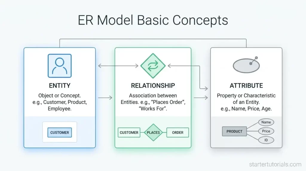
Before building a complex database, you need a clear visual blueprint to organize your data and prevent costly design mistakes. Learning ER model basic concepts gives you the foundational tools to map out real-world information using standard Entity-Relationship modeling fundamentals.
In this tutorial, we will break down the essential components of an ER diagram, including entities, attributes, and relationships; and explore how these core database modeling principles help you bridge the gap between initial ideas and real SQL tables.
What is an ER model?
An ER Model (Entity-Relationship Model) is a high-level visual blueprint used to design databases before writing any code or creating actual tables. Think of it like an architect’s floor plan: before building a house, you draw rooms, doors, and how they connect. An ER model does the exact same thing for your data.
The three core building blocks
Every ER model relies on three basic elements:
- Entities (The “Nouns”)
- What it is: Real-world objects, people, or concepts you want to store information about.
- Shape in Diagram: Rectangle
- Examples: Student, Course, Customer, Order
- Attributes (The “Adjectives”)
- What it is: The properties, characteristics, or details that describe an entity.
- Shape in Diagram: Oval / Ellipse
- Examples: For a Student entity, the attributes might be Student_ID, Name, and Email.
- Relationships (The “Verbs”)
- What it is: The connections or interactions between different entities.
- Shape in Diagram: Diamond
- Examples: A Student Enrolls In a Course.
Entity
An entity is an object in the real world that is distinguishable from others.
Ex 1: Student named Ramesh in II CSE 2/6 section 1
Ex 2: Student named Pooja in II CSE 2/6 section 1
Ex 3: CSE department in AU engineering college
Ex 4: HoD of CSE department in AU engineering college
Entity set
An entity set is a collection of similar entities. The entity sets need not be disjoint.
Ex 1: Students in CSE department
Ex 2: Faculty in CSE department
Ex 3: Systems in CSE labs
Ex 4: Employees working in AU engineering college
Attribute
An entity is described in the database using a set of attributes. All entities in a given entity set have same attributes. Each attribute will have a domain of possible values.
As an example, the attributes of Student entity are:
- Student ID
- Student name
- Student email
- Student mobile
- Student address
Relationship
A relationship is an association between two or more entities. For example, Ramesh studies in CSE department.
A collection of similar relationships is called as a relationship set.
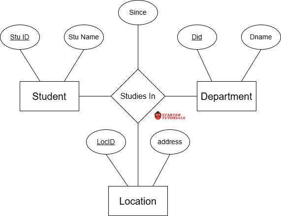
A relationship can have attributes called descriptive attributes. They are used to record information about the relationship.
A relationship having association between three entity sets is called a ternary relationship.
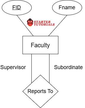
The entity sets participating in a relation need not be distinct. Sometimes a relationship might involve two entities in the same entity set. In such case we use role indicators to signify the role played by an entity set.
Need for ER modeling
The main reason we need ER (Entity-Relationship) modeling is to plan before we build.
If you build a house without a blueprint, you might forget to add plumbing, put doors in the wrong places, or run out of space. Fixing a house after it’s built is extremely hard and expensive.
A database is the same way. An ER model is the architectural blueprint for your data.
The key reasons why ER modeling is needed are:
- Prevents costly mistakes: Changing a drawing on paper takes seconds. Changing a live database with millions of user records can crash an app, lose data, and cost thousands of dollars to fix.
- Bridges the tech & business gap: Database engineers and non-technical clients (like a business owner or project manager) speak different languages. An ER model uses simple boxes and lines that anyone can look at and understand.
- Prevents duplicate & messy data (redundancy): Without planning, you might accidentally store a customer’s address in five different places. An ER model helps you structure data efficiently so every piece of information has one clear place to live.
- Shows how everything connects: In complex systems, data depends on other data. An ER model clearly shows how a Customer links to an Order, which links to a Product, ensuring no logical connections are missed.
- Serves as a guide for developers: Once the ER diagram is approved, programmers can build the actual database code (SQL tables, primary keys, foreign keys) quickly without guessing how things should work.
ER diagram symbols and notation
Now let’s see the symbols and notation used for the basic elements in an ER diagram.
Entity or entity set
An entity or an entity set in an ER diagram is represented using a rectangle symbol. Consider the example of a Student entity. It can be represented as shown in the image below:

Attribute
An attribute in an ER diagram is represented using a oval or ellipse symbol. Consider the example of Student entity. The attributes of the Student entity can be represented as shown in the image below:
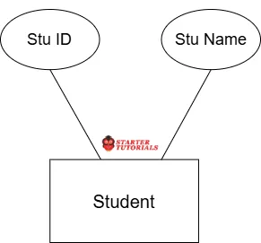
Remember that an attribute is always associated with an entity or with a relationship.
Relationship
A relationship between entities in an ER diagram is represented using a diamond symbol. Consider the relationship Enrolls In between the Student and Course entities. It can be represented as shown in the image below:
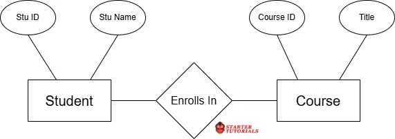
The above relationship is a binary relationship as it is between two entities. Similarly, we can have a relationship between three entities, which is called a ternary relationship. An example of ternary relationship is shown in the image below:
In some cases, we might need to represented a relationship on the same entity. Such a relationship is called a self or unary relationship. An example of self-relationship is shown in the image below:
ER diagram example
Let’s consider a university database. The simplified ER diagram considering only some of the entities and relationships in a university database is shown in the image below:
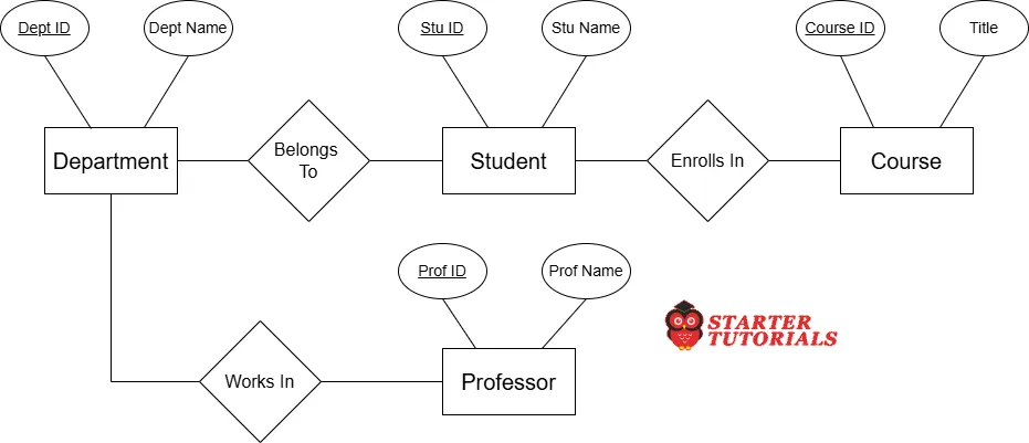
Following are the different elements in the above ER diagram:
Entity: Student
- Attributes: Stu ID, Stu Name
- Primary key: Stu ID
Entity: Department
- Attributes: Dept ID, Dept Name
- Primary key: Dept ID
Entity: Professor
- Attributes: Prof ID, Prof Name
- Primary key: Prof ID
Entity: Course
- Attributes: Course ID, Title
- Primary key: Course ID
Relationships
- Belongs To
- Enrolls In
- Works In
ER diagram design issues
When designing an ER diagram, we often have to make trade-offs on how to represent real-world concepts. The four common design issues to consider in ER modeling are explained with suitable examples below.
Choosing entity set vs. Attributes
The Dilemma: Should a piece of information be a standalone Entity (a main box) or just an Attribute (an oval attached to a box)?
- Rule of Thumb: If a piece of data has its own additional properties or needs to exist independently, make it an Entity. If it is just a simple value describing something else, make it an Attribute.
- University Example:
- Option A (Attribute): You treat Department as a simple string attribute inside the Instructor entity (e.g., Department_Name = “Computer Science”).
- Option B (Entity Set): You create Department as its own entity with attributes like Dept_Name, Building, and Budget.
- Decision: If the university only needs to record the department’s name, an attribute is fine. But if you need to track the department’s budget or location, Department must be its own Entity Set.
Choosing entity set vs. Relationship sets
The Dilemma: Should an action or event be represented as a Relationship connecting two entities, or elevated to its own separate Entity?
- Rule of Thumb: If an action just connects entities, keep it a Relationship. If that action has complex details, repeats over time, or connects to other things, convert it into an Entity Set.
- University Example:
- Relationship Approach: A Student takes a Course. You connect them using a diamond labeled Takes.
- Entity Set Approach: If a student takes the same course multiple times in different semesters, or if you need to store detailed records (like registration date, final grade, attendance, and fee status), Registration can become its own Entity Set placed between Student and Course.
Choosing binary vs. N-ary relationship sets
The Dilemma: Should a relationship connect two entities at once (Binary), or connect three or more entities together in a single relationship (N-ary / Ternary)?
- Rule of Thumb: Use a binary relationship whenever possible because n-ary relationships are harder to understand and convert into SQL. However, if an action involves three items happening simultaneously, an n-ary relationship may be necessary.
- University Example:
- Ternary (3-way) Relationship: Consider an instructor teaching a course in a specific classroom. The relationship Teaches connects three entities at once: Instructor, Course, and Classroom.
- Binary Alternative: Break it down into two separate binary relationships:
- Instructor Teaches Course.
- Course Assigned_To Classroom.
- Decision: If an instructor can teach the same course in different classrooms, breaking it into binary relationships simplifies the structure.
Placing relationship attributes
The Dilemma: When an attribute depends on a relationship happening, where should you attach the attribute—on one of the participating entities or directly on the relationship itself?
- Rule of Thumb: If an attribute belongs to the event rather than the individual items, attach it directly to the Relationship.
- University Example:
- Suppose a Student enrolls in a Course and receives a Grade.
- Where does Grade go?
- It cannot go in Student (a student has many different grades for different courses).
- It cannot go in Course (a course has many students with different grades).
- Decision: The Grade attribute belongs directly on the Enrolls_In relationship diamond, because a grade only exists when a specific student completes a specific course.
Advantages of ER model
The main advantage of an ER model is that it turns complex, messy database requirements into a simple visual map.
Here are the primary advantages explained simply:
- Very easy to understand: Because it uses basic shapes (rectangles, ovals, and diamonds), anyone from programmers to business owners can look at an ER diagram and quickly understand how data moves through a system.
- Saves time and money: Fixing a mistake on a diagram takes 30 seconds with an eraser. Fixing a mistake after a database is already built and full of real customer data can take days or weeks of coding work.
- Clear communication tool: Clients know what business rules they want, while database engineers know how to code them. The ER model acts as a shared language between non-technical clients and software developers.
- High-level visual blueprint: It provides a complete overview of the entire system’s structure at a glance before any actual code (like SQL) is written or hardware is set up.
- Easy to convert into real tables: Once an ER diagram is complete, database engineers can almost instantly map each entity directly into a real database table (Relational Model) with columns and primary keys.
- Prevents data confusion and redundancy: Mapping out connections beforehand helps organize data logically, preventing duplicate data and avoiding broken links between related information.
Disadvantages of ER model
While the ER model is great for planning, it does have a few drawbacks depending on the size and type of project. They are:
- Can become overcrowded and messy: For large systems (like Amazon or a major bank) with hundreds of entities and attributes, an ER diagram can become huge, cluttered, and almost impossible to read.
- Does not show how data changes over time: An ER model only shows the static structure of data; it shows what data exists and how it connects. It does not show how data flows, updates, or changes step-by-step during a business process.
- No standard industry rules (variations exist): Different designers and tools use slightly different shapes, symbols, and notations (like Chen notation vs. Crow’s Foot notation), which can sometimes cause confusion between team members.
- Not directly usable by computers: An ER model is purely a conceptual tool for humans. You cannot run an ER diagram directly in a database program like MySQL or PostgreSQL; it must first be manually converted into tables and SQL code.
- Difficult for unstructured or complex data: It works best for traditional tabular data. It struggles to represent unstructured data (like raw video files, audio clips, or modern graph networks) effectively.

Mr. P.S.Suryateja, also known as Suryateja Pericherla, is at present a Research Scholar (full-time Ph.D.) in the Dept. of Computer Science & Systems Engineering at Andhra University, Visakhapatnam. Previously worked as an Associate Professor in the Dept. of CSE at Vishnu Institute of Technology, India.
He has 14+ years of teaching experience and is an individual researcher whose research interests are Cloud Computing, Internet of Things, Computer Security, Network Security and Blockchain.
He is a member of professional societies like IEEE, ACM, CSI and ISCA. He published several research papers which are indexed by SCIE, WoS, Scopus, Springer and others.
Leave a Reply