Contents
Introduction
An activity diagram is like a flowchart, representing flow of control from activity to activity, whereas, the interaction diagrams focus on the flow of control from object to object.
Activities result in some action, which is made up of executable atomic computations that result in a change of state of the system or the return of a value.
Actions involve calling another operation, sending a signal, creating or destroying an object or some pure computation, such as evaluating an expression.
Common Properties
An activity diagram shares the same common properties as do all other UML diagrams like a name which is used to uniquely identify the diagram and the graphical content which is a projection into the model.
Content
Activity diagrams mainly contain:
- Activity states and action states
- Transitions
- Objects
Action States and Activity States
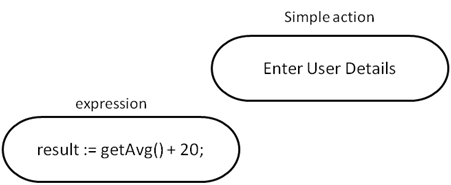
Activity diagram may represent actions which are atomic computations. These atomic computations are called action states because they are states of the system, each representing the execution of an action.
In UML, an action states is represented using a lozenge symbol (rounded rectangle) as shown below:
In contrast, activity states can be further decomposed, their activity being represented by other activity diagrams. Activity states are non-atomic and can be interrupted, considered to take some duration to complete.
There is no difference in the notation of activity states and action states except that the activity states may have additional information like entry and exit actions as shown below:
Transitions
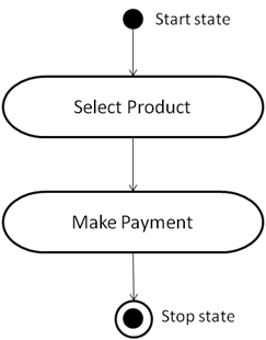
When the action or activity completes, the flow of control passes immediately to the next action or activity state. This flow is represented as transitions to show the path from one action or activity state to the next action or activity state.
In UML, a transition is represented as a simple directed line.
A flow of control has to start and end someplace. Therefore, as shown in the above figure, we can specify the initial state (solid ball) and stop state (a solid ball inside a hollow circle).
Branching
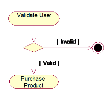
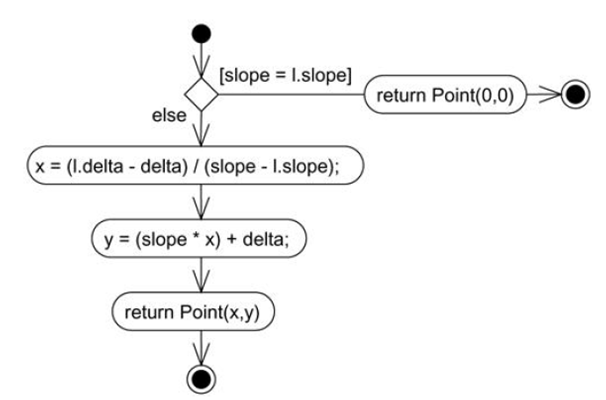
Like in flowcharts, we can include a branch, which specifies alternate paths taken based on some Boolean expression which is also known as a guard condition. In UML, a branch is represented as a diamond.
A branch may have one incoming transition and two or more outgoing transitions. Across all these outgoing transitions, guards should not overlap, but they should cover all possibilities.
Forking and Joining
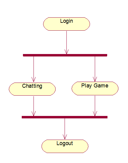
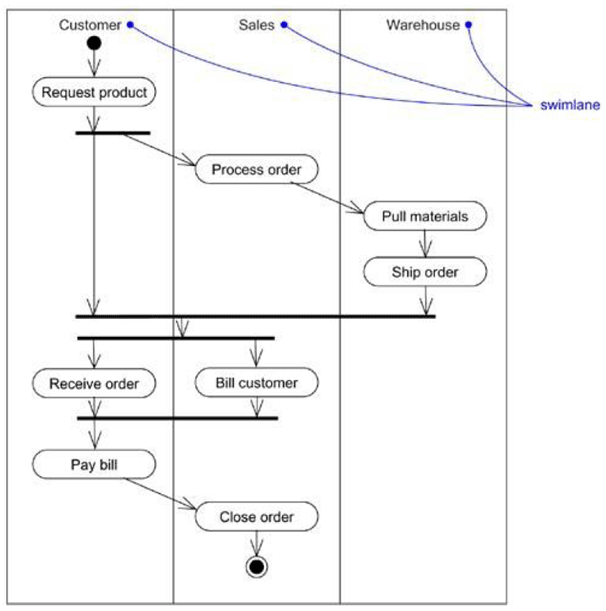
While modeling flow of control, it is common to encounter flows that are concurrent or parallel. In UML, a synchronization bar is used to specify the forking and joining of these parallel flows of control. A synchronization bar is represented as a thick vertical or horizontal line.
A fork may have one incoming transition and two or more outgoing transitions, each of which represents an independent flow of control. Below the fork, the activities in each flow carry out in parallel.
A join represents the synchronization of two or more concurrent flows of control. A join may have two or more incoming transitions and one outgoing transition. At the join, all the concurrent flows synchronize, meaning that each flow waits for the other to join and continues on below the join.
Swimlanes
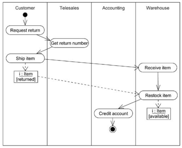
In activity diagrams, the activity states can be divided into logical groups, each group representing the object responsible for the activities. In UML, each group is known as a swimlane because, visually, each group is divided from its neighbor by a vertical solid line as shown in the below figure.
Each swimlane has its own name. In an activity diagram partitioned into swimlanes, every activity belongs to exactly one swimlane, but transitions may cross lanes.
Common Uses
When modeling the dynamic aspects of a system, you’ll use activity diagrams in two of the following ways:
- To model a workflow
- To model an operation
Common Modeling Techniques
Modeling a Workflow
To model a workflow:
- Establish a focus for the workflow.
- Select the objects that have the high-level responsibilities for parts of the overall workflow. Create a swimlane for each of these objects.
- Identify the pre-conditions of the workflow’s initial state and the post-conditions of the workflow’s final state.
- Starting at the workflow’s initial state layout the actions and activities that take place and render them as actions states or activity states.
- For complex actions, or for sets of actions that appear multiple times, collapse them into activity states and provide a separate activity diagram for them.
- Connect the action and activity states by transitions. Consider branching and then consider forking and joining.
- If there are important objects that are involved in the workflow, render them in the activity diagram as well.
Modeling an operation
To model an operation:
- Collect the abstractions involved in an operation like: parameters, attributes of the enclosing class and the neighboring class.
- Identify the operation’s pre-conditions and the operation’s post-conditions.
- Beginning at the operation’s initial state, define the actions and activities and render them as action states and activity states respectively.
- Use branching as necessary to specify conditional paths and iteration.
- If this operation is owned by an active class, use forking and joining as necessary to specify parallel flows of control.

Suryateja Pericherla, at present is a Research Scholar (full-time Ph.D.) in the Dept. of Computer Science & Systems Engineering at Andhra University, Visakhapatnam. Previously worked as an Associate Professor in the Dept. of CSE at Vishnu Institute of Technology, India.
He has 11+ years of teaching experience and is an individual researcher whose research interests are Cloud Computing, Internet of Things, Computer Security, Network Security and Blockchain.
He is a member of professional societies like IEEE, ACM, CSI and ISCA. He published several research papers which are indexed by SCIE, WoS, Scopus, Springer and others.

Please find this comprehensive activity diagram tutorial with examples for further learning. There are templates that you can edit straightaway to get started.