In this article we will look at famous IoT development boards like NodeMCU, Arduino Uno, Raspberry Pi, etc.
NodeMCU
NodeMCU is an open-source Lua based firmware developed for the ESP8266 wifi chip. By exploring functionality with the ESP8266 chip, NodeMCU firmware comes with the ESP8266 Development board/kit i.e. NodeMCU Development board. Since NodeMCU is an open-source platform, its hardware design is open for edit/modify/build. NodeMCU Dev Kit/board consist of ESP8266 wifi enabled chip.
Watch this video to understand about NodeMCU development board:
The ESP8266 is a low-cost Wi-Fi chip developed by Espressif Systems with TCP/IP protocol. There is Version2 (V2) available for NodeMCU Dev Kit i.e. NodeMCU Development Board v1.0 (Version2), which usually comes in black colored PCB. NodeMCU Dev Kit has Arduino like Analog (i.e. A0) and Digital (D0-D8) pins on its board. It supports serial communication protocols i.e. UART, SPI, I2C, etc.
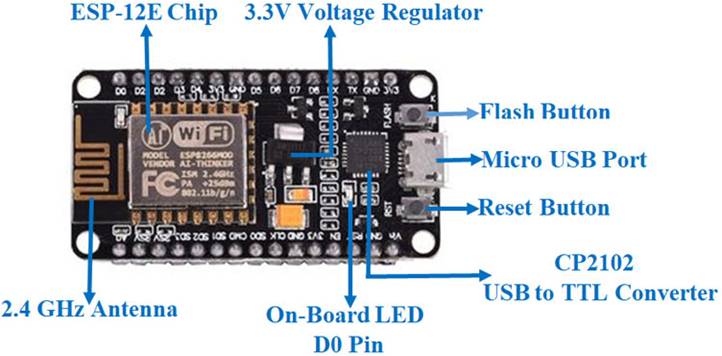
Using such serial protocols we can connect it with serial devices like I2C enabled LCD display, Magnetometer HMC5883, MPU-6050 Gyrometer + Accelerometer, RTC chips, GPS modules, touch screen displays, SD cards, etc. After setting up ESP8266 with Node-MCU firmware, we can use an IDE (Integrated Development Environment) for the development of NodeMCU. Different components on NodeMCU v2 development board are as shown in the figure below.
NodeMCU ESP8266 specification & features are as follows:
- Microcontroller: Tensilica 32-bit RISC CPU Xtensa LX106
- Operating Voltage: 3.3V
- Input Voltage: 7-12V
- Digital I/O Pins (DIO): 16
- Analog Input Pins (ADC): 1
- UARTs: 1
- SPIs: 1
- I2Cs: 1
- Flash Memory: 4 MB
- SRAM: 64 KB
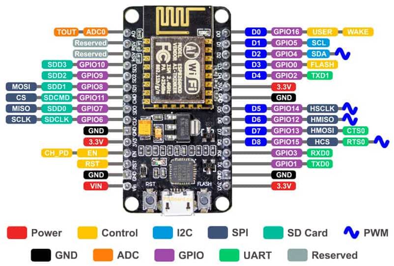
NodeMCU pin out diagram is as shown below.
Power Pins
- There are four power pins. VIN pin and three 3.3V pins.
- VIN can be used to directly supply the NodeMCU/ESP8266 and its peripherals. Power delivered on VIN is regulated through the onboard regulator on the NodeMCU module – you can also supply 5V regulated to the VIN pin,
- 3V pins are the output of the onboard voltage regulator and can be used to supply power to external components.
GND
- Are the ground pins of NodeMCU/ESP8266
I2C Pins
- Are used to connect I2C sensors and peripherals. Both I2C Master and I2C Slave are supported. I2C interface functionality can be realized programmatically, and the clock frequency is 100 kHz at a maximum. It should be noted that I2C clock frequency should be higher than the slowest clock frequency of the slave device.
GPIO Pins
- NodeMCU/ESP8266 has 17 GPIO pins which can be assigned to functions such as I2C, I2S, UART, PWM, IR Remote Control, LED Light and Button programmatically. Each digital enabled GPIO can be configured to internal pull-up or pull-down, or set to high impedance. When configured as an input, it can also be set to edge-trigger or level-trigger to generate CPU interrupts.
ADC Channel
- The NodeMCU is embedded with a 10-bit precision SAR ADC. The two functions can be implemented using ADC. Testing power supply voltage of VDD3P3 pin and testing input voltage of TOUT pin. However, they cannot be implemented at the same time.
UART Pins
- NodeMCU/ESP8266 has 2 UART interfaces (UART0 and UART1) which provide asynchronous communication (RS232 and RS485), and can communicate at up to 4.5 Mbps. UART0 (TXD0, RXD0, RST0 & CTS0 pins) can be used for communication. However, UART1 (TXD1 pin) features only data transmit signal so, it is usually used for printing log.
SPI Pins
- NodeMCU/ESP8266 features two SPIs (SPI and HSPI) in slave and master modes. These SPIs also support the following general-purpose SPI features:
- 4 timing modes of the SPI format transfer
- Up to 80 MHz and the divided clocks of 80 MHz
- Up to 64-Byte FIFO
SDIO Pins
- NodeMCU/ESP8266 features Secure Digital Input/Output Interface (SDIO) which is used to directly interface SD cards. 4-bit 25 MHz SDIO v1.1 and 4-bit 50 MHz SDIO v2.0 are supported.
PWM Pins
- The board has 4 channels of Pulse Width Modulation (PWM). The PWM output can be implemented programmatically and used for driving digital motors and LEDs. PWM frequency range is adjustable from 1000 μs to 10000 μs (100 Hz and 1 kHz).
Control Pins
- Are used to control the NodeMCU/ESP8266. These pins include Chip Enable pin (EN), Reset pin (RST) and WAKE pin.
- EN: The ESP8266 chip is enabled when EN pin is pulled HIGH. When pulled LOW the chip works at minimum power.
- RST: RST pin is used to reset the ESP8266 chip.
- WAKE: Wake pin is used to wake the chip from deep-sleep.
ESP8266
ESP8266 is Wi-Fi enabled system on chip (SoC) module developed by Espressif system. It is mostly used for development of IoT (Internet of Things) embedded applications. It employs a 32-bit RISC CPU based on the Tensilica Xtensa L106 running at 80 MHz (or overclocked to 160 MHz). It has a 64 KB boot ROM, 64 KB instruction RAM and 96 KB data RAM. ESP8266 module is low cost standalone wireless transceiver that can be used for end-point IoT developments.
Watch this video to learn about ESP8266:
ESP8266 comes with the following capabilities:
- 4 GHz Wi-Fi (802.11 b/g/n, supporting WPA/WPA2)
- general-purpose input/output (16 GPIO)
- Inter-Integrated Circuit (I²C) serial communication protocol
- analog-to-digital conversion (10-bit ADC)
- Serial Peripheral Interface (SPI) serial communication protocol
- I²S (Inter-IC Sound) interfaces with DMA(Direct Memory Access) (sharing pins with GPIO)
- UART (on dedicated pins, plus a transmit-only UART can be enabled on GPIO2)
- pulse-width modulation (PWM)
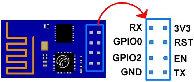
The pin out specification for ESP8266 is as shown below.
Arduino
Arduino is an open-source platform used for building electronics projects. Arduino consists of both a physical programmable circuit board (often referred to as a microcontroller) and a piece of software, or IDE (Integrated Development Environment) that runs on your computer, used to write and upload computer code to the physical board.
Watch this video to learn about Arduino board:
Unlike most previous programmable circuit boards, the Arduino does not need a separate piece of hardware (called a programmer) in order to load new code onto the board you can simply use a USB cable. Arduino IDE uses a simplified version of C++, making it easier to learn to program.
The key features of Arduino are:
- Arduino boards are able to read analog or digital input signals from different sensors and turn it into an output such as activating a motor, turning LED on/off, connect to the cloud and many other actions.
- You can control your board functions by sending a set of instructions to the microcontroller on the board via Arduino IDE (referred to as uploading software).
- Finally, Arduino provides a standard form factor that breaks the functions of the micro-controller into a more accessible package.
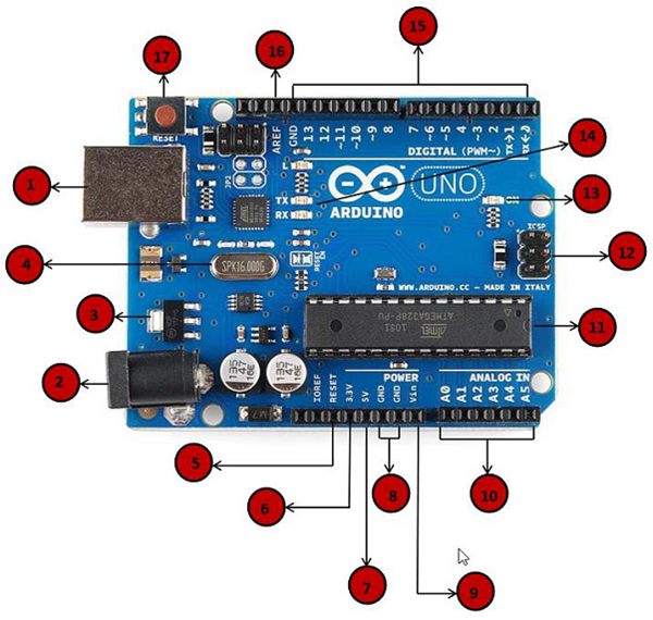
Different components in Arduino Uno board are shown in the below figure.
{1} Power USB
- Arduino board can be powered by using the USB cable from your computer. All you need to do is connect the USB cable to the USB connection.
{2} Power (Barrel Jack)
- Arduino boards can be powered directly from the AC mains power supply by connecting it to the Barrel Jack.
{3} Voltage Regulator
- The function of the voltage regulator is to control the voltage given to the Arduino board and stabilize the DC voltages used by the processor and other elements.
{4} Crystal Oscillator
- The crystal oscillator helps Arduino in dealing with time issues. How does Arduino calculate time? The answer is, by using the crystal oscillator. The number printed on top of the Arduino crystal is 16.000H9H. It tells us that the frequency is 16,000,000 Hertz or 16 MHz.
{5} Arduino Reset
- You can reset your Arduino board, i.e., start your program from the beginning. You can reset the UNO board in two ways. First, by using the reset button (17) on the board. Second, you can connect an external reset button to the Arduino pin labelled RESET.
Pins (3.3, 5, GND, Vin)
- {6} 3.3V − Supply 3.3 output volt
- {7} 5V − Supply 5 output volt
- Most of the components used with Arduino board works fine with 3.3 volt and 5 volt.
- {8} GND(Ground) − There are several GND pins on the Arduino, any of which can be used to ground your circuit.
- {9} Vin − This pin also can be used to power the Arduino board from an external power source, like AC mains power supply.
{10} Analog pins
- The Arduino UNO board has six analog input pins A0 through A5. These pins can read the signal from an analog sensor like the humidity sensor or temperature sensor and convert it into a digital value that can be read by the microprocessor.
{11} Main microcontroller
- Each Arduino board has its own microcontroller. You can assume it as the brain of your board. The main IC (integrated circuit) on the Arduino is slightly different from board to board. The microcontrollers are usually of the ATMEL Company. You must know what IC your board has before loading up a new program from the Arduino IDE. This information is available on the top of the IC. For more details about the IC construction and functions, you can refer to the data sheet.
{12} ICSP pin
- Mostly, ICSP is an AVR, a tiny programming header for the Arduino consisting of MOSI, MISO, SCK, RESET, VCC, and GND. It is often referred to as an SPI (Serial Peripheral Interface), which could be considered as an “expansion” of the output. Actually, you are slaving the output device to the master of the SPI bus.
{13} Power LED indicator
- This LED should light up when you plug your Arduino into a power source to indicate that your board is powered up correctly. If this light does not turn on, then there is something wrong with the connection.
{14} TX and RX LEDs
- On your board, you will find two labels: TX (transmit) and RX (receive). They appear in two places on the Arduino UNO board. First, at the digital pins 0 and 1, to indicate the pins responsible for serial communication. Second, the TX and RX led. The TX led flashes with different speed while sending the serial data. The speed of flashing depends on the baud rate used by the board. RX flashes during the receiving process.
{15} Digital I/O
- The Arduino UNO board has 14 digital I/O pins (of which 6 provide PWM (Pulse Width Modulation) output. These pins can be configured to work as input digital pins to read logic values (0 or 1) or as digital output pins to drive different modules like LEDs, relays, etc. The pins labeled “~” can be used to generate PWM.
{16} AREF
- AREF stands for Analog Reference. It is sometimes, used to set an external reference voltage (between 0 and 5 Volts) as the upper limit for the analog input pins.
Intel Galileo
Galileo is a microcontroller board based on the Intel® Quark SoC X1000 Application Processor, a 32-bit Intel Pentium-class system on a chip. It’s the first board based on Intel® architecture designed to be hardware and software pin-compatible with Arduino shields designed for the Uno R3.
Watch this video to learn about Intel Galileo board:
The 32-bit processor can run at up to 400MHz, and it has 512 KB SRAM built-in. There’s 8MB Flash (to store firmware), an 11KB EEPROM (non-volatile memory), and a µSD socket (which supports up to 32GB µSD cards).
In addition to the memory, there are all sorts of peripherals: 10/100Mb Ethernet, USB 2.0 host and device ports, an RS-232 port, and a mini PCI Express (mPCIE) socket. What the Galileo tries to do is meld the ease of Arduino’s hardware manipulation with the power of a fully operational Linux operating system.
You still have access to popular Arduino libraries like SD, Ethernet, WiFi, EEPROM, SPI, and Wire, but you can also access the Linux side of the board with system() calls. The Linux half of the board supports stuff like Python, Node.js, SSH, Telnet, and all sorts of other, fun Linux stuff.
Different components on Intel Galileo board as shown in the figure below.
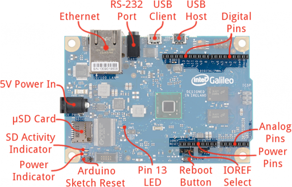
Ethernet
- Connects the Galileo up to any 10/100 Mb/s LAN.
RS-232 Port
- In a weird, 3.5mm “stereo” jack form factor. The sleeve is ground, ring is TX, and tip is RX. With the proper cables, this can be used to access the Linux terminal.
USB Client
- Connect this to your computer to program the Galileo with Arduino.
USB 2.0 Host
- This supports an interface with USB devices like keyboards, mass storage, etc. With a USB hub, up to 128 devices can be connected to this port.
Standard Arduino connectors
- 8-pin power header (3.3V, 5V, GND, Reset, etc.)
- 6-pin analog input header (A0-A6)
- 8-pin digital I/O header (D0-D7), which includes UART on pins 0/1, PWM on pins 3, 5, and 6
- 10-pin digital I/O header (D8-SCL), which includes I2C pins and PWM on pins 9, 10, and 11.
- 2×3-pin ICSP header breaks out SPI pins.
Reboot Button
- Pressing this button will reboot the entire Galileo — Linux included. Boot time is about 30 seconds, so don’t press this accidentally.
Pin 13 LED
- As with most Arduinos, the Galileo ties a small, on-board LED to pin 13. Great for the Blink sketch.
Arduino Reset Button
- This will restart solely the Arduino sketch running on the Galileo. This button acts much more like the reset button you may be used to.
µSD Card
- The Galileo supports up to 32GB SD cards. You’ll have to use this socket if you hope to boot the Galileo off the “bigger” Linux image.
5V Power In
- This is a center-positive, 2.1mm barrel jack for a clean, regulated 5V supply. The power supply should be included with your Galileo.
Raspberry Pi
Raspberry Pi is a small single board computer. By connecting peripherals like Keyboard, mouse, display to the Raspberry Pi, it will act as a mini personal computer. Raspberry Pi is popularly used for real time Image/Video Processing, IoT based applications and Robotics applications. Raspberry Pi is slower than laptop or desktop but is still a computer which can provide all the expected features or abilities, at a low power consumption.
Watch this video to learn about Raspberry Pi board:
Raspberry Pi Foundation officially provides Debian based Raspbian OS. Also, they provide NOOBS OS for Raspberry Pi. We can install several Third-Party versions of OS like Ubuntu, Archlinux, RISC OS, Windows 10 IOT Core, Kali etc. Raspbian OS is official Operating System available for free to use. This OS is efficiently optimized to use with Raspberry Pi.
Raspbian have GUI which includes tools for Browsing, Python programming, office, games, etc. We should use SD card (minimum 8 GB recommended) to store the OS (Operating System). Raspberry Pi is more than computer as it provides access to the on-chip hardware i.e. GPIOs for developing an application. By accessing GPIO, we can connect devices like LED, motors, sensors, etc and can control them too.
It has ARM based Broadcom Processor SoC along with on-chip GPU (Graphics Processing Unit). The CPU speed of Raspberry Pi varies from 700 MHz to 1.2 GHz. SDRAM that ranges from 256 MB to 1 GB. Raspberry Pi also provides on-chip SPI, I2C, I2S and UART modules.
There are different versions of raspberry pi available as listed below:
- Raspberry Pi 1 Model A
- Raspberry Pi 1 Model A+
- Raspberry Pi 1 Model B
- Raspberry Pi 1 Model B+
- Raspberry Pi 2 Model B
- Raspberry Pi 3 Model B
- Raspberry Pi 3 Model B+
- Raspberry Pi 4 Model B
- Raspberry Pi Zero
Different components on Raspberry Pi 4 Model B board are as shown in the figure below.
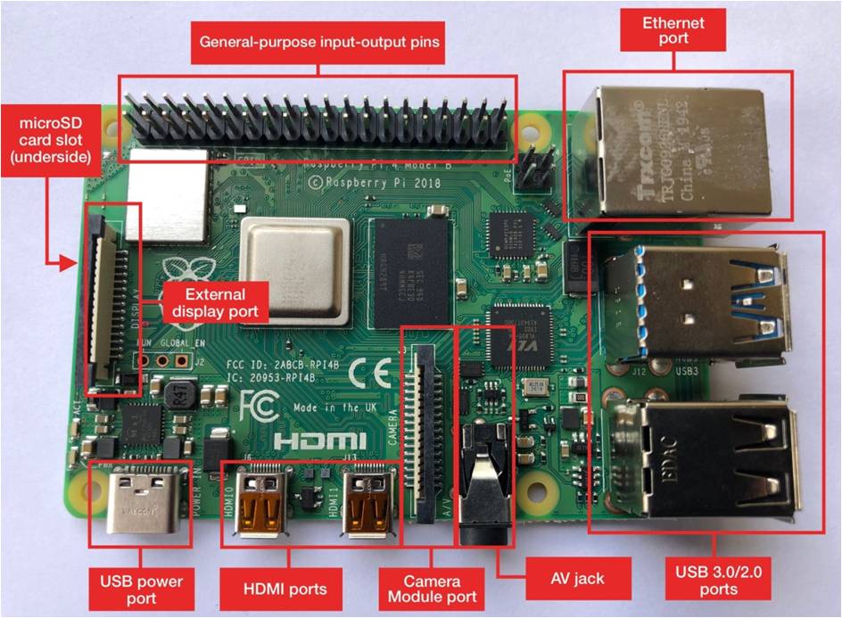
The Raspberry Pi 4 board contains the following components:
- General-purpose input–output pins: These pins are used to connect the Raspberry Pi to electronic components
- Ethernet port: This port connects the Raspberry Pi to a wired network. The Raspberry Pi also has Wi-Fi and Bluetooth built in for wireless connections
- Two USB 3.0 and two USB 2.0 ports: These USB ports are used to connect peripherals like a keyboard or mouse. The two black ports are USB 2.0 and the two blue ports are USB 3.0
- AV jack: This AV jack allows you to connect speakers or headphones to the Raspberry Pi
- Camera Module port: This port is used to connect the official Raspberry Pi Camera Module, which enables the Raspberry Pi to capture images
- HDMI ports: These HDMI ports connect the Raspberry Pi to external monitors. The Raspberry Pi 4 features two micro HDMI ports, allowing it to drive two separate monitors at the same time
- USB power port: This USB port powers the Raspberry Pi. The Raspberry Pi 4 has a USB Type-C port, while older versions of the Pi have a micro-USB port
- External display port: This port is used to connect the official seven-inch Raspberry Pi touch display for touch-based input on the Raspberry Pi
- microSD card slot (underside of the board): This card slot is for the microSD card that contains the Raspberry Pi operating system and files
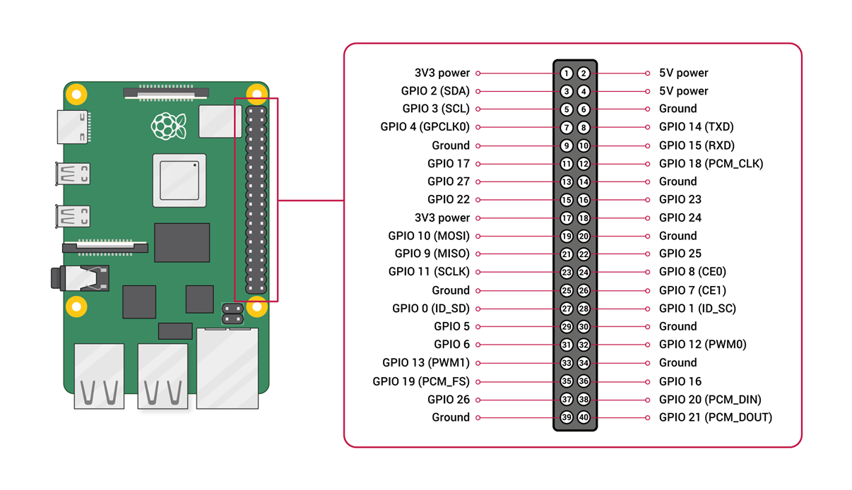
The pin out diagram for Raspberry Pi board is as shown below.

Suryateja Pericherla, at present is a Research Scholar (full-time Ph.D.) in the Dept. of Computer Science & Systems Engineering at Andhra University, Visakhapatnam. Previously worked as an Associate Professor in the Dept. of CSE at Vishnu Institute of Technology, India.
He has 11+ years of teaching experience and is an individual researcher whose research interests are Cloud Computing, Internet of Things, Computer Security, Network Security and Blockchain.
He is a member of professional societies like IEEE, ACM, CSI and ISCA. He published several research papers which are indexed by SCIE, WoS, Scopus, Springer and others.
Leave a Reply