In this article we will learn about different wireless protocols for IoT like RFID, IEEE 802.15.4, 6LoWPAN, WiFi, LiFi, and others.
Contents
Introduction to Wireless Protocols for IoT
The issues related to choosing a certain technology for a particular solution are network topology, power consumption, transmission power efficiency, and latency. Development and deployment of protocols focus on the following issues:
- Medium access techniques
- Data rate
- Communication mode
- Transmission range
- Power consumption
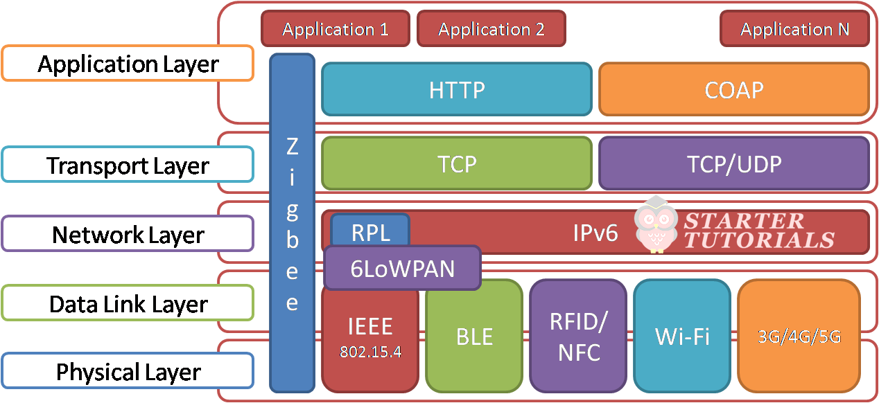
An overview of the wireless protocols in IoT with respect to TCP/IP stack is shown in the below figure.
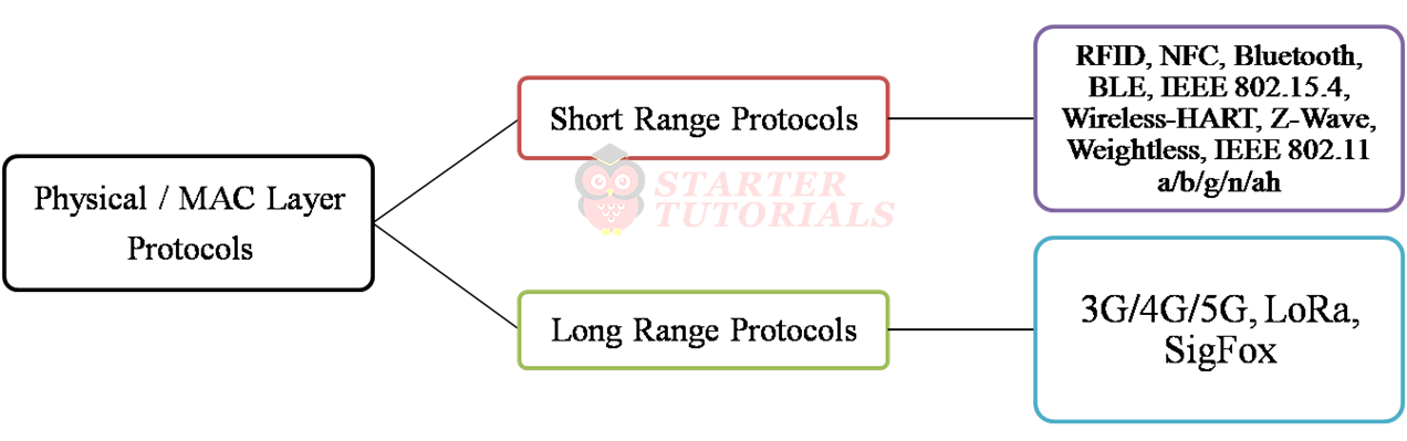
The classification of link layer protocols based on range supported is shown below.
RFID
Radio Frequency Identification (RFID) refers to a set of technologies that are aimed at identifying and recognizing elements (tags)
Watch this video to lean about RFID technology:
[arve url=”https://www.youtube.com/watch?v=MRZnCCqqtns” title=”Internet of Things (IoT) Lecture 13 – RFID” description=”In this internet of things (IoT) lecture, you will learn about the following: OSI Model and TCP/IP Model Introduction to Wireless Protocols (An Overview) Physical and MAC layer protocols classfication RFID” upload_date=”2020-10-06″ thumbnail=”https://i3.ytimg.com/vi/MRZnCCqqtns/maxresdefault.jpg” aspect_ratio=”4:3″ /]
An RFID system is basically composed of two types of devices (see figure below):
- Devices to be identified (tags)
- Device identifiers (readers)
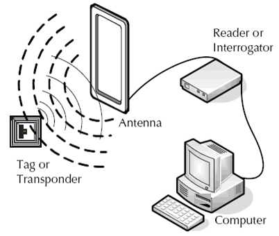
Tagged devices are triggered by RF (Radio Frequency) waves emitted by the reader devices and reply its identification (ID) tags. Readers handle data exchange between them. When necessary, readers send RF pulses interrogating the tags in the area. Tags reply to this question by submitting their tag Ids. Transmission of data takes place depending on the proximity of the tag to the reader device, even though it does not have line of sight (LOS).
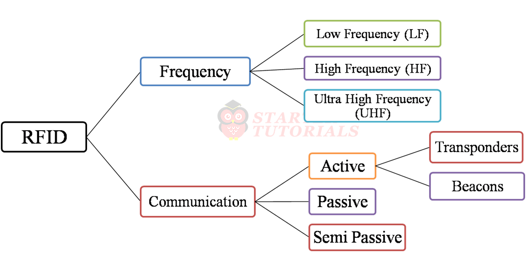
The classification of RFID devices based on frequency and communication is as shown in the figure below.
Bluetooth
WPAN IEEE 802.15.1 also called the Bluetooth Basic Rate (BR) is a global 2.4 GHz specification working with short-range wireless networking. The different versions of Bluetooth are as follows:
- v1.0
- v1.0B (voice dialling, call mute, 10m range)
- v1.2 (adaptive frequency hopping)
- v2.0 + Enhanced Data Rates (EDR)
- v2.1 + EDR
- Improved resistance to radio frequency interference
- Improved indoor range and LOS range to 100m
- Fast transmission speed
- Low power consumption mechanisms
- v3.0
- Enhanced power control to quickly adapt to the changing path loss of the new 5GHz transmission band
- v4.0
- Increased modulation index resulting in less energy during transmission
- v4.1
- Better alignment in pico-nets timing when the transmission suffers interference
- v4.2
- Low energy is reinforced with the adoption of longer packet transmissions
- v5.0
- Improvements in transmission and receiving
- v5.1
- Released in 2019
Watch this video to learn about Bluetooth technology:
[arve url=”https://www.youtube.com/watch?v=djEykHteyZI” title=”Internet of Things (IoT) Lecture 14 – Bluetooth” description=”In this internet of things (IoT) lecture, you will learn about the following: Introduction to Bluetooth Bluetooth versions Bluetooth protocol stack against OSI model Piconet and Scatternet” upload_date=”2020-10-08″ thumbnail=”https://i3.ytimg.com/vi/MRZnCCqqtns/maxresdefault.jpg” aspect_ratio=”4:3″ /]
The mapping of OSI reference model to IEEE 802.15.1 Bluetooth stack is given below.
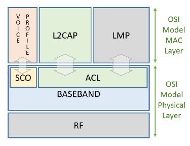
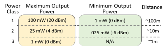
The Radio and the Base-band sub-layers define the Bluetooth physical layer. The Radio layer provides the physical links among Bluetooth devices with 79 different Radio Frequency (RF) channels spaced of 1 MHz, using a Frequency Hopping Spread Spectrum (FHSS) transmission technique. This FHSS technique increases the robustness of the link due to its capability to reduce the interference of nearby systems that may operate in the same frequency range. Bluetooth power class classification is as shown in the below figure.
The Base-band Layer defined by the IEEE 802.15.1 standard operates in the 2.4-GHz Industrial Scientific and Medical (ISM) band using a short-range radio link and a Fast Frequency-Hopping (FFH) transceiver. The main roles of the Bluetooth MAC layer are to:
- set-up the physical connections between the master and slaves
- send and receive packets along the physical channels
- synchronize the network devices with the master clock and manage the different devices for power saving states
A Link Management Protocol (LMP) is a control protocol responsible to establish base-band and physical layer links. Functions such as connection establishment and release, among others, are Link Management (LM) features. LMP handles a Synchronous Connection-Oriented (SCO) link, and an Asynchronous Connectionless Link (ACL) link.
A SCO physical link establishment is a symmetric point-to-point connection between the master and a specific slave. It is used to deliver delay-sensitive traffic, such as voice service, and works as a circuit-switched connection between the master and the slave. The ACL link is a point (master) to multi-point (slaves) in a pico-net domain and works as a packet-switched connection.
To ensure the integrity of the data and to guarantee a reliable delivery of the data, ACL uses a fast Automatic Repeat Request scheme. The Logical Link Control and Adaptation Protocol (L2CAP) layer is a channel-based abstraction between the base-band and service application layer. The L2CAP layer handles segmentation and reassembly of application data, and multiplexing and de-multiplexing of multiple channels over a shared logical link.
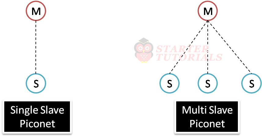
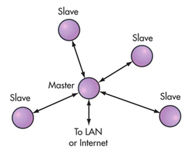
Bluetooth relies on the contention-free token-based multi-access networks as logical topology. End point devices are mentioned as slaves. A cluster of up to seven slave devices can be attached to a master device, in order to have access to the channel, composing a piconet cellular topology. The master is responsible to manage the polling process messages to authorize a slave device to access the channel and transmit its data.
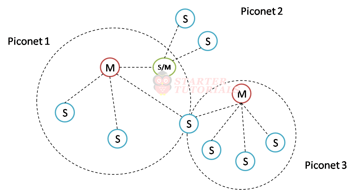
The coverage areas of the piconets can be overlapped forming a scatternet topology when at least one unit exchanges data with more than one master. This allows a slave to be active in more than one piconet at the same time but can be managed by only one master element. A size of a piconet is limited to just one master and up to seven active slave stations. Piconet can be illustrated as shown below.
A scatternet can be formed by combining piconets as shown in the below figure.
The differences between piconet and scatternet are as follows:
| Piconet | Scatternet |
| Device can function either a master or slave | Device can function as master or salve or as master+slave |
| Server smaller coverage area | Serves larger coverage area |
| Supports maximum 8 nodes | Supports more than 8 nodes |
| Less efficient use of bandwidth | More efficient use of bandwidth |
BLE
Bluetooth v4.0 standard is also called as Bluetooth Low Energy (BLE). BLE is also known as Smart Bluetooth. BLE is an IEEE 802.15.1 variation with better and more suitable capacities for low power applications. Devices that demand communication with both standards of Bluetooth need to implement both protocol stacks.
Watch this video to learn about BLE in IoT:
[arve url=”https://www.youtube.com/watch?v=LWG3zyqYaBQ” title=”Internet of Things (IoT) Lecture 15 – Bluetooth Low Energy” description=”In this internet of things (IoT) lecture, you will learn about the following: Introduction to Bluetooth Low Energy (BLE) Star topology in BLE BLE protocol stack against OSI model Bluetooth Basic Rate vs. BLE” upload_date=”2020-10-19″ thumbnail=”https://i3.ytimg.com/vi/MRZnCCqqtns/maxresdefault.jpg” aspect_ratio=”4:3″ /]
Star is the only topology accepted by BLE. Any data exchanged between two slave devices shall pass through the unique master. A slave device may not be connected to two master units at the same time. Using a similar protocol stack as classic Bluetooth, the differences between them starts above the L2CAP layer. The star topology is as shown below.
BLE protocol stack can be illustrated as shown below.
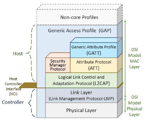
The two main roles of BLE are: controller and host. BLE differs from the classical Bluetooth in the controller stack that defines the association methods of the devices. A slave can belong to only one piconet during an association lifetime, and is synchronized with only one master element. Link layer manages events generated by the hosts, at determined time intervals, using the advertising channels.
Bidirectional data flow is obtained with a connection between elements, when slaves advertising packets are received by master elements. The energy save handling done at MAC layer can put the slaves in a sleeping mode by default and waking them periodically through a Time Division Multiple Access (TDMA) scheme. Data exchange between the application layer and link layer are also done by L2CAP using no retransmission techniques or flow control mechanisms as used on the classic Bluetooth.
When two devices are connected under a server and client association architecture, the server needs to maintain a set of attributes. The Attribute Protocol (ATT) handles the attributes of this connection like the definition of data structure used to store the information managed by the Generic Attribute Profile (GATT) that works on top of the ATT. GATT defines the client or server functionalities of a connection and this association is independent of the master or slave roles.
A framework defined by GATT performs the role of discovery services using the ATT attributes, and allows exchange of characteristics between devices interconnected. An attribute carries a set of characteristics that includes a value and properties of the parameter monitored by the device. For example, a humidity sensor needs humidity characteristics and attributes to describe this sensor, and to store its measurements.
Creating specific profiles with the Low Energy Bluetooth standard takes place in the Generic Attribute Profile (GAP). GATT uses the Attribute Protocol (ATT) protocol in addition to the lower stack protocols, in order to introduce the subdivision of retained server attributes into services and features. Services can contain a set of features, which can include a single value (accessible from the client) and other numerical data that describe such features.
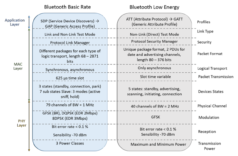
Bluetooth is designed to offer a low-cost alternative to Wi-Fi at the expense of the transmission range. Its transmission range is considerably shorter (up to 100 m LOS). BLE operates at 1Mbps rate on its physical layer, while its application layer can handle only 236.7 Kbps. Differences between Bluetooth and BLE are as shown in the figure below.
IEEE 802.15.4
IEEE 802.15.4 is a subgroup of features that refers to physical and medium access control layers that can support ZigBee and 6LoWPAN. IEEE 802.15.4 focuses on physical and data link layer specifications. It defines PHY and MAC layers for personal area networks that demand low rate and low cost applications. This is also called a LR-WPAN (Low Rate Wireless Personal Area Network) protocol. It has the following advantages:
- simple and flexible protocol stack
- low cost
- low energy consumption
- short-range operation
- reliable data transfer
- ease of operation
These features are more important when operating in the Personal Operating Space (POS) also defined as Personal Area Network (PAN) that involves the human body.
Watch this video to learn about IEEE 802.15.4 protocol and Wi-Fi technology:
[arve url=”https://www.youtube.com/watch?v=oWiHrV5YSiM” title=”IEEE 802.15.4 and Wi-Fi” description=”In this internet of things (IoT) lecture, you will learn about the following: – Introduction to IEEE 802.15.4 (LR-WPAN) – IEEE 802.15.4 compared with OSI model – IEEE 802.15.4 star and peer-to-peer topologies – Introduction to Wi-Fi – 802.11 wireless standards – Wi-Fi 802.1l ah standard” upload_date=”2020-10-20″ thumbnail=”https://i3.ytimg.com/vi/oWiHrV5YSiM/maxresdefault.jpg” aspect_ratio=”4:3″/]
An IEEE 802.15.4 device address can be a short 16-bit or 64-bit address. In addition, IEEE 802.15.4 uses a Direct Sequence Spread Spectrum (DSSS) access mode and operates on 2450 MHz, 915 MHz, and 868 MHz ISM bands working with 16 channels, 10 channels, and one channel, respectively. IEEE 802.15.4 compared with OSI reference model looks as shown below.
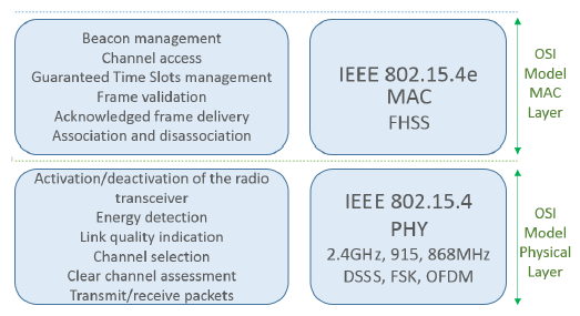
Physical layer is responsible for:
- activation, and deactivation of the radio transceiver
- energy detection (ED) within the current channel
- link quality indication (LQI) for received packets
- clear channel assessment (CCA) for carrier sense multiple access with collision avoidance (CSMA-CA)
- channel frequency selection
- data transmission and reception
The energy saving aspects of IEEE 802.15.4 are mainly addressed to this layer by the ED, LQI and CCA functionalities. The IEEE 802.15.4MAC layer provides access to the physical channel for all upper layers, providing two kinds of services:
- The MAC data service
- The MAC management service
The standard defines two different methods of channel access that are a beacon enabled (BE) mode and a non-beacon-enabled (NBE) mode. The MAC sub-layer is responsible for:
- beacon management
- channel access
- Guaranteed Time Slots (GTS) management
- frame validation
- delivered frame acknowledgement
- association/disassociation activities
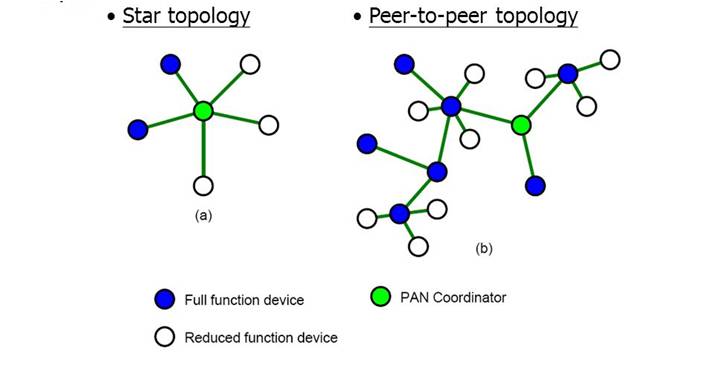
The star and peer-to-peer topology of IEEE 802.15.4 looks as shown in the figure below.
Wi-Fi
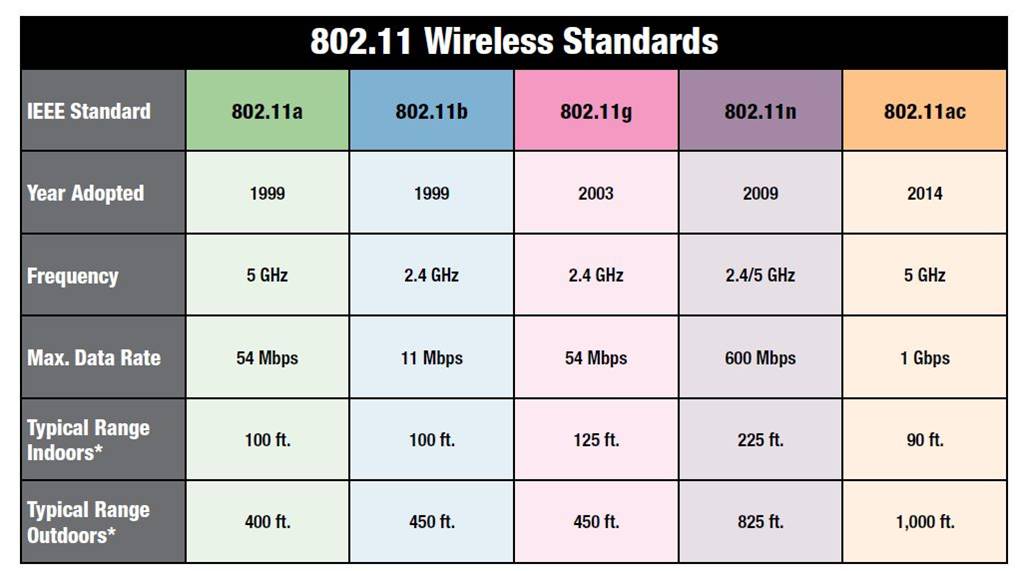
Wi-Fi is standardized by IEEE as protocol for WLAN. Its technology has evolved to meet the needs of increasingly specific demands. This evolution has initiated a group of IEEE 802.11 standards that have been merged, and named Wireless Fidelity (Wi-Fi). Wi-Fi Alliance is a group that certifies Wi-Fi products. Diiferent 802.11 wireless standards is given below.
The standard defines that communication devices are referred to as Stations (STAs) and can behave independently. Communication is directly between the two devices forming an ad hoc topology. The star topology happens when a certain STA is defined to be the traffic concentration point of other STAs, becoming an Access Point (AP). A STA-AP has a defined coverage area called the Basic Service Area (BSA) that allows it to associate with several STAs, forming a Basic Service Set (BSS).
The STA-AP is usually connected to the internet or to a WAN network through a wired connection. While the IEEE focuses on defining the PHY and MAC layers of the protocol as a grouped context, the Wi-Fi Alliance aims to work on the physical layer to facilitate peer-to-peer communications. The IEEE 802.11 standard has evolved since its first release in 1997. The PHY layer has evolved to work on the 2.4 GHz and 5 GHz ISM frequency bands.
The multiple transmission beam-forming technology improves the transmission and reception parameters and, consequently, transmission rates with greater values from 2 Mbps on IEEE 802.11 up to 600 Mbps for IEEE 802.11n. The MAC layer of IEEE 802.11 has as its main differential the mechanism of access to carrier sense multiple access with collision avoidance (CSMA/CA) as a medium access method. Features such as MAC level acknowledgments, fragmentation and reassembly, inter frame gaps and exponential back-off algorithm, roaming, security and power saving mechanisms are adopted by IEEE 802.11.
With Machine to Machine (M2M) communications emerging, it was necessary to adjust the IEEE 802.11 standard that was primarily designed for computer communication. M2M communication demands distinct characteristics such as transmission range above 1 Km, transmission rates higher than 100 Kbps and low power consumption. There is also a need to have a network that supports a large number of nodes, operating under a policy of lower power consumption.
In an attempt to meet these requirements, the IEEE 802.11ah Task Group (TGah) has guided the necessary improvements in the PHY and MAC layers of the IEEE 802.11 protocol to suit this scenario. The IEEE 802.11ah can be used not only as WSN but as well as back-haul infrastructure to connect the sensors to the data collectors. This is possible due to its large coverage and data rates capability.
The IEEE 802.11ah amendment comes to solve some important limitations encountered to use Wi-Fi IEEE 802.11a/b/g/n when used to M2M communications. Although there is a need to maintain connection and synchronization with the APs, the IEEE 802.11ah terminals are equipped with mechanisms that provide energy saving during the period of inactivity. This ensures that the IEEE 802.11ah features long range and low power consumption when compared to other WLAN technologies, but remaining different from LP-WANs.
6LoWPAN
6LoWPAN abbreviates to IPv6 over Low-Power Wireless Personal Area Networks. 6LoWPAN is a networking technology. It acts as an adaptation layer that allows IPv6 packets to be carried efficiently within small link layer frames, such as those defined by IEEE 802.15.4.
Watch this video to learn about 6LoWPAN:
[arve url=”https://www.youtube.com/watch?v=udXmbDGPrug” title=”Internet of Things (IoT) Lecture 17 – 6LoWPAN” description=”In this internet of things (IoT) lecture, you will learn about the following: Introduction to 6LoWPAN 6LoWPAN mesh network 6LoWPAN network architecture 6LoWPAN system stack overview 6LoWPAN adaptation layer Routing in 6LoWPAN Security in 6LoWPAN” upload_date=”2020-10-22″ thumbnail=”https://i3.ytimg.com/vi/udXmbDGPrug/maxresdefault.jpg” aspect_ratio=”4:3″ /]
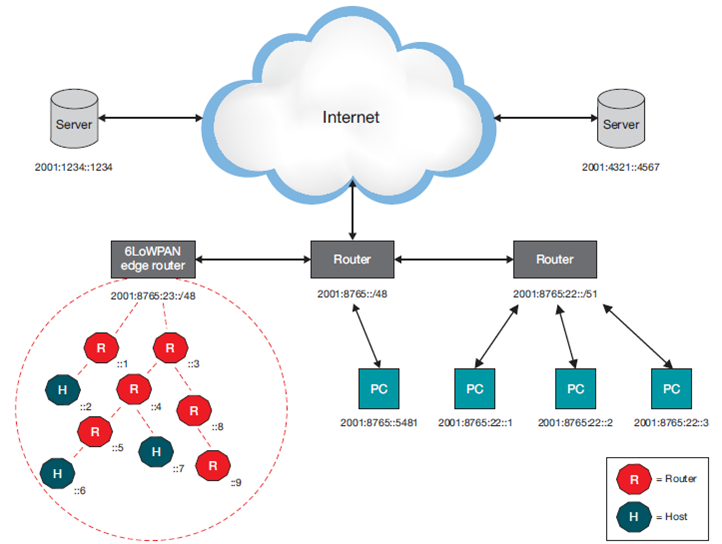
6LoWPAN is an open standard defined in RFC 6282 by the Internet Engineering Task Force (IETF). 6LoWPAN was originally conceived to support IEEE 802.15.4 low-power wireless networks in the 2.4-GHz band. Now being adapted and used over a variety of other networking media including Bluetooth Smart, low-power Wi-Fi, etc. An example of an IPv6 network with a 6LoWPAN mesh network is given below.
6LoWPAN network architecture
The uplink to the Internet is handled by the Access Point (AP) acting as an IPv6 router. Several different devices are connected to the AP in a typical setup, such as PCs, servers, etc. The 6LoWPAN network is connected to the IPv6 network using an edge router. The edge router handles three actions:
- the data exchange between 6LoWPAN devices and the Internet (or other IPv6 network)
- local data exchange between devices inside the 6LoWPAN
- the generation and maintenance of the radio subnet (the 6LoWPAN network)
One 6LoWPAN network may be connected to other IP networks through one or more edge routers that forward IP datagrams between different media. Connectivity to other IP networks may be provided through any arbitrary link, such as Ethernet, Wi-Fi or 3G/4G. Because edge routers forward datagrams at the network layer, they do not maintain any application-layer state. Two device types are included inside a typical 6LoWPAN network: routers and hosts.
Routers can, as the name implies, route data destined to another node in the 6LoWPAN network. Hosts are also known as end devices and are not able to route data to other devices in the network. Host can also be a sleepy device, waking up periodically to check its parent (a router) for data, enabling very low power consumption.
System Stack Overview
6LoWPAN radically changes the IoT landscape. Until now a complex application layer gateway was needed to make devices such as ZigBee, Bluetooth and proprietary systems connect to the Internet. 6LoWPAN solves this dilemma by introducing an adaptation layer between the IP stack’s link and network layers to enable transmission of IPv6 datagrams over IEEE 802.15.4 radio links. The 6LoWPAN stack compared to WiFi and OSI stack is given below.
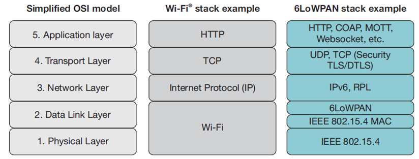
The physical layer converts data bits into signals that are transmitted and received over the air. The data link layer provides a reliable link between two directly connected nodes by detecting and correcting errors that may occur in the physical layer during transmission and receiving.
The data link layer includes the media access layer (MAC) which provides access to the media. This layer also handles data framing. In the 6LoWPAN example, the MAC layer is IEEE 802.15.4. The 6LoWPAN adaptation layer, providing adaptation from IPv6 to IEEE 802.15.4, also resides in the link layer. The network layer addresses and routes data through the network, if needed over several hops.
IP (or Internet Protocol) is the networking protocol used to provide all devices with an IP address to transport packets from one device to another. The transport layer generates communication sessions between applications running on end devices. Finally, the application layer is responsible for data formatting. A broadly used application layer on the Internet is HTTP running over TCP.
Internet Protocol version 6 (IPv6) over IEEE 802.15.4
Due to resource constraints and 6LoWPAN multi-hop topology, supporting IPv6 over IEEE 802.15.4 networks present several challenges:
- IPv6 datagrams are not a natural fit for IEEE 802.15.4 networks
- Low throughput, limited buffering and datagrams that are one-tenth of IPv6 minimum MTU make header compression and data fragmentation a necessity
- Since IEEE 802.15.4 is both low power and low throughput, in addition to the use of RF as media, it is more prone to spurious interference, link failures and asymmetric links
- The most common network topology for 6LoWPAN is a low-power mesh network
- This negates the assumption that a link is a single broadcast domain, something that is very important since the very foundation of IPv6 such as neighbour discovery relies on it
The 6LoWPAN adaptation layer
When sending data over MAC and PHY layers, an adaptation layer is always used. The main focus of the IETF working group, 6LoWPAN WG, was to optimize the transmission of IPv6 packets over low-power and lossy networks (LLNs) such as IEEE 802.15.4 and led to the following:
- Header compression
- Fragmentation and reassembly
- Stateless auto configuration
Routing
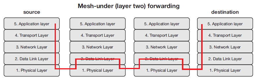
Routing is the ability to send a data packet from one device to another device, sometimes over multiple hops. Depending on what layer the routing mechanism is located, two categories of routing are defined: mesh-under or route-over. Mesh-under uses the layer-two (link layer) addresses (IEEE 802.15.4 MAC or short address) to forward data packets. Route-over uses layer three (network layer) addresses (IP addresses).
Mesh-under routing
- In a mesh-under system, routing of data happens transparently, hence mesh-under networks are considered to be one IP subnet
- The only IP router in such a system is the edge router
- Messages have to be sent to all devices in the network, resulting in high network load
- Mesh-under networks are best suited for smaller and local networks
Mesh under routing can be seen in the below figure.
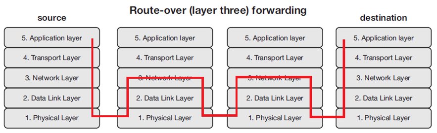
Route-over routing
- In route-over networks the routing takes place at the IP level, thus each hop in such networks represents one IP router
- The most widely used routing protocol for route-over 6LoWPAN networks today is RPL (pronounced “ripple”)
- Route-over features the advantage that most of the protocols used on a standard TCP/IP stack today can be implemented and used as is
- RPL supports two different routing modes: storing mode and non-storing mode
Route over routing can be seen in the below figure.
Security
Due to the nature of IoT with many nodes that in many cases have very constrained performance, there are also more entry points for an outside attacker. The damage potential is much higher since the data flowing in the system can be used to open the door to you house or turn on/off alarms remotely. 6LoWPAN takes advantage of the strong AES-128 link layer security defined in IEEE 802.15.4.
The link layer security provides link authentication and encryption. In addition to link layer security, transport layer security (TLS) mechanisms have been shown to work great in 6LoWPAN systems. For constrained environments and systems where UDP is chosen as the transport layer protocol, Datagram Transport Layer Security (DTLS) is used. However, it should be noted that implementing TLS/DTLS requires the device to have necessary resources, such as a hardware encryption engine.
Zigbee
ZigBee is one of the most popularly deployed wireless technologies in recent years. ZigBee is a new open-standard wireless protocol developed by ZigBee Alliance (consisting of over 270 companies).
Watch this video to learn about ZigBee technology:
[arve url=”https://www.youtube.com/watch?v=qQTsr4MZnnM” title=”Internet of Things (IoT) Lecture 18 – Zigbee” description=”In this internet of things (IoT) lecture, you will learn about the following: Introduction to Zigbee Wi-Fi vs. Bluetooth vs. Zigbee Zigbee Protocol Stack Zigbee Device Types Zigbee Topologies Zigbee Security” upload_date=”2020-10-26″ thumbnail=”https://i3.ytimg.com/vi/udXmbDGPrug/maxresdefault.jpg” aspect_ratio=”4:3″ /]
ZigBee is an open standard, lightweight, low-cost, low-speed, low-power protocol that allows true operability between systems. It is built on existing IEEE 802.15.4 protocol. Zigbee can support up to 65,000 nodes depending on the type of topology used. The comparison between WiFi, Bluetooth and Zigbee are as given below.
| Features | Wi-Fi 802.11 | Bluetooth 802.15.1 | Zibgee 802.15.4 |
| Application | Wireless LAN | Cable Replacement | Control and Monitor |
| Frequency | 2.4 GHz | 2.4 GHz | 2.4 GHz, 868 MHz, 915 MHz |
| Battery Life (Days) | 0.1 – 5 | 1 – 7 | 100 – 7000 |
| Nodes Per Network | 30 | 7 | 65000 |
| Bandwidth | 2-100 Mbps | 1 Mbps | 20-250 Kbps |
| Range (Meters) | 1 – 100 | 1 – 10 | 1 – 75 and more |
| Topology | Tree | Tree | Star, Tree, Cluster Tree, Mesh |
| Memory | 100 KB | 100 KB | 32 – 60 KB |
History of ZigBee:
- ZigBee started back in 1998 when it was first conceived and supported from development perspective
- ZigBee Alliance published its first ratified specification in 2004
- In 2006, the 2004 specification was modified to support group addressing, encryption and frame authenticity
- In 2007, ZigBee 2007 and ZigBee Pro was published
- ZigBee 2007 added new security model to ZigBee 2006 with trust centre
- ZigBee-Pro has additional software features, more scalability, data fragmentation, stochastic addressing (automated address allocation mechanism) and enhanced security
- ZigBee 2007 and ZigBee-Pro are interoperable
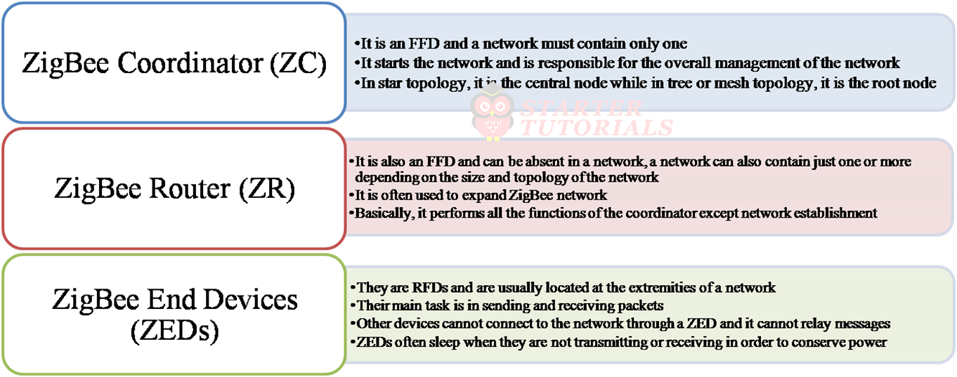
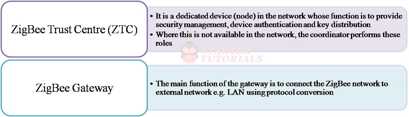
Zibgee Device Types
The operation of a ZigBee node depends on whether it is a Full Function Device (FFD) or Reduced Function Device (RFD). The FFD performs all the tasks defined by ZigBee standard. The function performed by the RFD is limited. An FFD can form any type of network (such as star, tree or mesh).RFD can only connect to an FFD. Different device types in Zigbee are shown below.
Zibgee Network Topologies
Star Topology
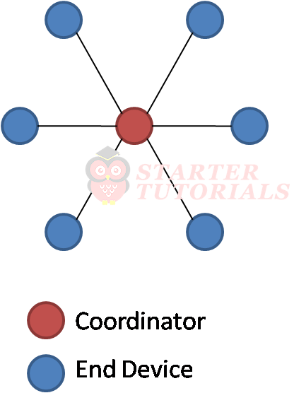
The star topology consists of a coordinator and several end devices. It has no router and therefore a star network has a depth of one. End devices communicate with each other in the network only through the coordinator. The major advantage of a ZigBee star network is its simplicity.
The main disadvantage is that it does not provide alternative route for packet transmission and reception. All transmission and reception go through the coordinator. This may increase the burden on the coordinator and hence cause congestion in the network. The star topology is as shown below.
Tree Topology
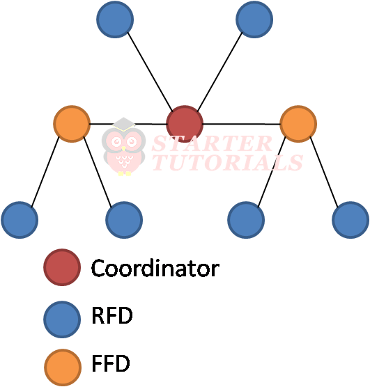
In the tree topology, the coordinator (at the top) is connected to several routers and end devices. The router is used to extend the network. A router can therefore connect to several other routers and/or end devices to form the router’s children.
Only the coordinator and the routers can have children and hence can become parents in a tree topology. The end devices cannot have children and therefore cannot become parents. A child is only permitted to communicate directly with its parent and not with any other nodes.
Parents can communicate directly with their parents and children. If a parent is down, its children cannot communicate with other nodes in the network. Even if two nodes in the network are geographically close, their direct communication is not guaranteed. The topology is as shown below.
Mesh Topology
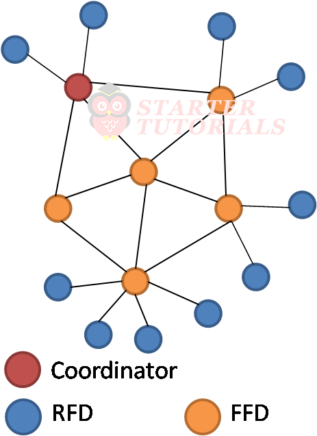
In mesh, the coordinator is also at the top like that of tree. It consists of a coordinator, several routers and end devices. Routers are used to extend network range like in tree. Packets pass through multiple hops to reach destination.
It is also called a peer-to-peer multi-hop network. A mesh network provides alternative paths for packet to reach its destination if a path fails. Mesh network is usually also described as a “self-healing” network. Compared to star and tree configurations, mesh network is more complex and therefore requires more overhead and uses more complex routing protocols. The mesh network is as shown below.
Zibgee Protocol Stack
Two types of addresses are in use in ZigBee network: IEEE address and network address. The IEEE address is a unique 64-bit long address used to identify a ZigBee device. It is assigned to the device by the manufacturer and is also called MAC address or extended address. No two devices can have the same IEEE address in the entire world.
The network address (otherwise known as short address) is a 16-bit address that identifies a node locally in the network. It is assigned by a parent to a node when the node joins the network.
The advantage of using the 16-bit address is that it extends battery life. A 16-bit address reduces frame size compared to a 64-bit address size and hence reduces transmission time and consequently, increases battery life. The disadvantage is that it is possible for two nodes on different networks to have the same short address. The ZigBee protocol stack is as shown below.
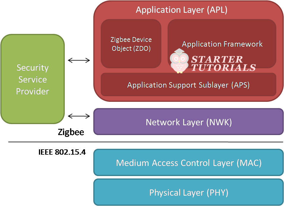
The ZigBee stack is formed on top of the IEEE 802.15.4 standard. The IEEE 802.15.4 consists of the Physical (PHY) and Media Access Control (MAC) layers. ZigBee layer is made up of:
- Network (NWK) layer
- Application Support Sublayer (APS)
- ZigBee Device Object (ZDO)
- Security Service
ZigBee Physical Layer
The main function of the physical layer is to modulate outgoing signals and demodulate incoming signals. Deals with transmission and reception of information from sources. The physical layer frequency band consists of 27 channels which are used worldwide. Like IEEE 802.11, ZigBee uses mandatory DSSS (Distributed Sequence Spread Spectrum) and optional PSSS (Parallel Sequence Spread Spectrum).
ZigBee MAC layer
This layer access the network using CSMA/CA (carrier-sense multiple access with collision avoidance) to enable beacon transmission for synchronization and hence provide reliable transmission. Assigning device roles (ZC, ZR, or ZED), topology design, and network association and disassociation. At MAC layer, ZigBee traffics are carried by frames, unlike WiFi and Bluetooth. The frames are beacon frames, data frames, acknowledge frames and command frames.
ZigBee Network Layer
This layer is located between MAC and Application layer. The main functions of the network layer includes:
- network establishment
- address assigning
- routing and neighbour discovery
- adding and removing devices from the network
- applying security features to outgoing messages
ZigBee Application Layer
The application layer is the highest layer in the ZigBee protocol stack. It interfaces a ZigBee system (application object) with its end user. Application layer is made up of:
- ZigBee Device Object (ZDO)
- Application Support Sublayer (APS)
- Application Framework
The ZDO Layer assigns functions to all ZigBee devices in the network. It determines whether a device is a coordinator, a router or an end device. It also performs security related functions (such as setting and removal of encryption key) and network management functions (such as network discovery).
The APS Layer enables the interfacing of ZigBee endpoints (application objects) and ZDO with the network layer for network services such as data and management services. Services include request, confirm and response, which are provided to the objects for reliable and efficient data transfer.
Security
The security service plane spans and interacts with the NKW and APS layers. ZigBee security provides authentication, integrity, freshness and privacy in a ZigBee network. Security is provided using counter mode encryption and cipher block chaining message authentication code (CCM) at different levels with 128 bit Advanced Encryption Standard (AES) algorithm. For all levels of security, ZigBee uses symmetric key and applies cryptography and frame integrity to network and application layers.
It is the responsibility of an application developer to decide the level of security to apply. A layer is also responsible to protect (secure) a frame that it generated. ZigBee uses 3 types of keys for security:
- Link key: This is used by the APS layer to protect confidentiality and integrity of unicast traffic between two devices.
- Network key: This is used to protect and secure group or broadcast traffic in the network.
- Master key: This key is optional. Where applicable, it can be used to generate other keys (network and link keys).
4G & 5G
4G
4G stands for “Fourth Generation”, which refers to the fourth generation of cellular communication. 4G has the capabilities to download at speeds of 1Gbps when stationary and 100 Mbps while mobile. The International Telecommunications Union (ITU) has designated two technological formats to be 4G, which are:
- LTE Advanced (Long Term Evolution Advanced)
- WiMax Release 2
Watch this video to learn about 4G and 5G technologies:
[arve url=”https://www.youtube.com/watch?v=a0FSgIoez2E” title=”Internet of Things (IoT) Lecture 19 – 4G & 5G” description=”In this internet of things (IoT) lecture, you will learn about the following: Introduction to 4G 4G Features 4G Technologies – LTE Advanced, WiMax Release 2, HSPA+ 4G Applications 4G Devices Difference between 3G and 4G Introduction to 5G 5G Features” upload_date=”2020-10-27″ thumbnail=”https://i3.ytimg.com/vi/a0FSgIoez2E/maxresdefault.jpg” aspect_ratio=”4:3″ /]
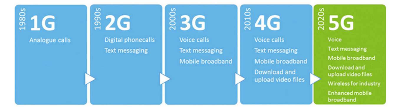
Different generations of cellular communication can be seen in the below figure. 4G offers all features of 3G and:
- On-demand video
- Video conferencing
- High quality streaming video
- High quality Voice-over-IP (VoIP)
- Added security features
LTE
Stands for Long Term Evolution and has been adopted by Verizon, AT&T and Metro PCS. LTE operates on the radio frequency and the cellular network to transmit voice and data. It uses pre-coded version of OFDM (Orthogonal Frequency Division Multiplex) for uplink and normal OFDM for the downlink. LTE is also backwards compatible and can be easily upgraded to LTE Advanced. LTE specification indicates that LTE wireless internet could provide a downstream rate of at least 100Mbps and upstream rate of at least 50Mbps.
WiMax
Stands for Worldwide Interoperability for Microwave Access and is also known also as IEEE 802.16. WiMax technology can operate at speeds up to 4Mbps and a bandwidth of up to 75Mbps with a range of up to 30 miles. WiMAX operates on licensed spectrum where frequencies are exclusively allocated to the carriers. Thus, the operators will be able to emit more power without fear of interference.
HSPA+
Stands for Evolved High Speed Packet Access and has been adopted by T-Mobile and AT&T. HSPA+ will be implemented in a series of phases. 64 QAM (Quadrature Amplitude Modulation) for the first phase. 64 QAM plus advanced antenna techniques such as 2X2 MIMO for the second phase. First phase can provide theoretical speeds of up to 21Mbps. Second phase can provide theoretical speeds of up to 42MBps.
Since 4G is capable of much faster speeds than previous technologies, 4G is capable of providing more applications that require larger bandwidths such as:
- Wireless Broadband Internet Access
- MMS (Multimedia Messaging Service)
- Video Chat
- Mobile Television
- HDTV (High Definition TV)
- DVB (Digital Video Broadcasting)
- Real Time Audio
- High Speed Data Transfer
There are many types of devices that currently use 4G technology that include:
- Mobile phones
- Laptops and PCs
- Tablets
- Video Camera
- Gaming Devices
- Vending Machines
- Refrigerators
- Billing Devices
The differences between 3G and 4G are as shown below:
| 3G | 4G | |
| Frequency Band | 1.8-2.5 GHz | 2-8 GHz |
| Bandwidth | 5-20 MHz | 5-20 MHz |
| Data Rate | Up to 2Mbps | Up to 20Mbps or more |
| Access | Wideband CDMA | Multi-Carrier CDMA or OFDM |
| Switching | Circuit / Packet | Packet |
5G
5G is the 5th generation mobile network. It is a new global wireless standard after 1G, 2G, 3G, and 4G networks. 5G enables a new kind of network that is designed to connect virtually everyone and everything together including machines, objects, and devices. 5G wireless technology is meant to deliver higher multi-Gbps peak data speeds, ultra low latency, more reliability, massive network capacity, increased availability, and a more uniform user experience to more users.
5G is based on OFDM (Orthogonal frequency-division multiplexing), a method of modulating a digital signal across several different channels to reduce interference. 5G also uses wider bandwidth technologies such as sub-6 GHz and mmWave. 5G will bring wider bandwidths by expanding the usage of spectrum resources, from sub-3 GHz used in 4G to 100 GHz and beyond.
5G is designed to not only deliver faster, better mobile broadband services compared to 4G LTE, but can also expand into new service areas such as mission-critical communications and connecting the massive IoT. There are several reasons that 5G will be better than 4G:
- 5G is significantly faster than 4G
- 5G has more capacity than 4G
- 5G has significantly lower latency than 4G
- 5G is a unified platform that is more capable than 4G
- 5G uses spectrum better than 4G
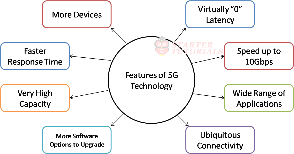
5G is used across three main types of connected services, including enhanced mobile broadband, mission-critical communications, and the massive IoT. 5G is designed to deliver peak data rates up to 20 Gbps. The features of 5G technology are illustrated in the below figure.
Li-Fi
Li-Fi (Light Fidelity) technology was proposed by the German physicist named Harald Haas. Li-Fi is similar to Wi-Fi technology and it is one of the future wireless communication technologies. The data transmission in this technology can be done using light because the light intensity changes quicker than the human eye for capturing. The speed of data transmission in Li-Fi is 100 times faster than Wi-Fi.
Watch this video to learn about Li-Fi and LPWAN technologies:
[arve url=”https://www.youtube.com/watch?v=V_FeSyXVXwk” title=”Internet of Things (IoT) Lecture 20 – Li-Fi and LPWAN” description=”In this internet of things (IoT) lecture, you will learn about the following: Introduction to Li-Fi How Li-Fi Works? Differences between Li-Fi and Wi-Fi Advantages and Disadvantages of Li-Fi Introduction to LPWAN LPWAN Wireless Technologies General Terminology in LPWANs Comparison of LPWAN Wireless Technologies” upload_date=”2020-10-30″ thumbnail=”https://i3.ytimg.com/vi/V_FeSyXVXwk/maxresdefault.jpg” aspect_ratio=”4:3″ /]
How Li-Fi Works?
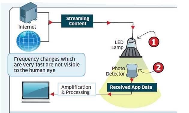
Li-Fi system mainly includes two parts namely the transmitter and receiver. The input signal at the transmitter section can be modulated with a specific time period then send the data using LED bulbs in 0’s and 1’s form. Here, the flashes of LED bulbs are denoted with 0’s and 1’s. At the receiver end, a photodiode is used to receive the LED flashes strengthens the signal & gives the output.
Li-Fi is a VLC (visible light communications) system and the speed of this system is very high. Li-Fi uses normal LEDs to allow the data to transfer and increase the speed up to 224 Gigabits/sec. The data transmission of this technology can be done via illumination. The essential devices of this system are the bright light emitting diodes. The working of Li-Fi as as shown in the below figure.
The differences between Li-Fi ad Wi-Fi are given below:
| Feature | Li-Fi | Wi-Fi |
| Full form | Light Fidelity | Wireless Fidelity |
| Operation | Li-Fi transmits data using light with the help of LED bulbs | Wi-Fi transmits data using radio waves with the help of Wi-Fi router |
| Interference | Less to no interference | Interference due to near by access points |
| Technology | IrDA compliant devices | WLAN 802.11 a/b/g/n/ac/ah compliant devices |
| Applications | Airlines, under water exploration, hospitals and more | Internet browsing |
| Advantages | Less interference, pass through water, works in dense regions | More available infrastructure |
| Privacy | As light is blocked through walls, more secure data transfer | As walls cannot block radio waves, techniques should be used for secure data transfer |
| Data Speed | 224 Gbps | 2 Gbps |
| Frequency | 10,000 times the spectrum of radio waves | 2.4 GHz, 4.9 GHz, 5 GHz |
| Data density | Works in high density environments | Works in less density environments due to interference issues |
| Coverage distance | 10 meters | 32 meters |
| System Components | Lamp driver, LED, Photo detector | Routers and End devices |
The advantages of Li-Fi technology are:
- High speed
- Security
- Harmless
- Consistent
The disadvantages of Li-Fi technology are:
- Line of sight problems
- Interference
- Dim areas
- Range problems
LPWAN
Low-Power Wide Area Networks (LPWANs) are wireless technologies with following characteristics:
- large coverage areas
- low bandwidth
- very small packets
- long battery life operation
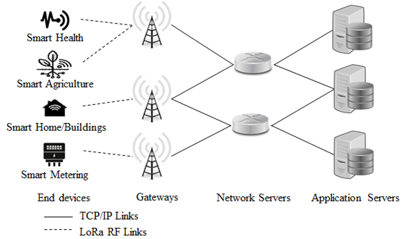
LPWA communication standards are designed for IoT use cases in the mentioned scope of wireless IoT connectivity with limited needs. Different LPWAN technologies are: LoRaWAN, Sigfox, NB-IoT, LTE-M, Wi-SUN. LPWAN technologies, have similar architectures but different terminology. Different types of entities in a typical LPWAN network are:
- End devices
- Radio Gateway
- Network Gateway or Router
- LPWAN-AAA server
- Application Server
The general terminology used across different LPWAN technologies are as shown in the table given below.
| Function/ Technology | LoRaWAN | NB-IoT | Sigfox | Wi-SUN | IETF |
| Sensor, Actuator, device, object | End Device | User Equipment | End Point | Leaf Node | Device (DEV) |
| Transceiver Antenna | Gateway | Evolved Node B | Base Station | Router Node | Radio Gateway |
| Server | Network Server | PDN GW / SCEF | Service Center | Border Router | Network Gateway (NGW) |
| Security Server | Join Server | Home Subscriber Service | Registration Authority | Authentication Server | LPWAN-AAA Server |
| Application | Application Server | Application Server | Network Application | Application | Application (App) |
The general architecture of LPWAN is as given below.

Suryateja Pericherla, at present is a Research Scholar (full-time Ph.D.) in the Dept. of Computer Science & Systems Engineering at Andhra University, Visakhapatnam. Previously worked as an Associate Professor in the Dept. of CSE at Vishnu Institute of Technology, India.
He has 11+ years of teaching experience and is an individual researcher whose research interests are Cloud Computing, Internet of Things, Computer Security, Network Security and Blockchain.
He is a member of professional societies like IEEE, ACM, CSI and ISCA. He published several research papers which are indexed by SCIE, WoS, Scopus, Springer and others.
Leave a Reply