First, let’s see what is the use of learning conceptual model of UML.
To learn a new language, for example, let’s consider English, we learn the character set (a-z) first and then the words and then several rules to form sentences using those words.
Similarly to learn using UML, we should learn the vocabulary and then rules for creating UML diagrams. The conceptual model of UML contains the UML’s vocabulary and rules. So, to understand using UML and to create using UML diagrams first we need to learn the conceptual model of UML.
The conceptual model of UML contains the fundamentals of UML. The conceptual model consists of three parts. They are:
1) Building blocks of UML (syntax / vocabulary)
2) Rules (semantics)
3) Common Mechanisms
Contents
Building blocks of UML (Conceptual model of UML)
These are the fundamental elements in UML. Every diagram can be represented using these building blocks. The building blocks of UML contains three types of elements. They are:
1) Things (object oriented parts of uml)
2) Relationships (relational parts of uml)
3) Diagrams
Things
A diagram can be viewed as a graph containing vertices and edges. In UML, vertices are replaced by things, and the edges are replaced by relationships. There are four types of things in UML. They are:
1) Structural things (nouns of uml – static parts)
2) Behavioral things (verbs of uml – dynamic parts)
3) Grouping things (organizational parts)
4) Annotational things (explanatory parts)
Structural things
Represents the static aspects of a software system. There are seven structural things in UML. They are:
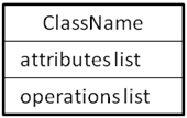
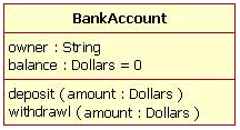
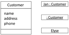
Class: A class is a collection of similar objects having similar attributes, behavior, relationships and semantics. Graphically class is represented as a rectangle with three compartments.
Graphical representation:
Example:
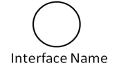
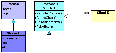
Interface: An interface is a collection of operation signatures and/or attribute definitions that ideally define a cohesive set of behavior. Graphically interface is represented as a circle or a class symbol stereotyped with interface.
Graphical representation:
or
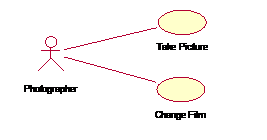
Use Case: A use case is a collection of actions, defining the interactions between a role (actor) and the system. Graphically use case is represented as a solid ellipse with its name written inside or below the ellipse.
Graphical representation:
Example:
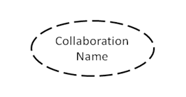
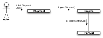
Collaboration: A collaboration is the collection of interactions among objects to achieve a goal. Graphically collaboration is represented as a dashed ellipse. A collaboration can be a collection of classes or other elements.
Graphical representation:
Example:
Component: A component is a physical and replaceable part of a system. Graphically component is represented as a tabbed rectangle. Examples of components are executable files, dll files, database tables, files and documents.
Graphical representation:
Example:
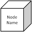
Node: A node is a physical element that exists at run time and represents a computational resource. Graphically node is represented as a cube. Examples of nodes are PCs, laptops, smartphones or any embedded system.
Graphical representation:
Example:
Active Class: A class whose objects can initiate its own flow of control (threads) and work in parallel with other objects. Graphically active class is represented as a rectangle with thick borders.
Graphical representation:
Example:
Behavioral Things
Represents the dynamic aspects of a software system. Behavior of a software system can be modeled as interactions or as a sequence of state changes.
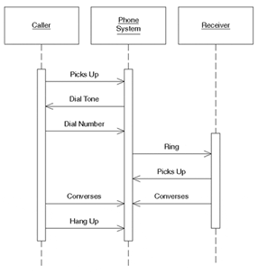
Interaction: A behavior made up of a set of messages exchanged among a set of objects to perform a particular task. A message is represented as a solid arrow. Below is an example of interaction representing a phone conversation:
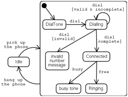
State Machine: A behavior that specifies the sequences of states an object or interaction goes through during its’ lifetime in response to events. A state is represented as a rectangle with rounded corners. Below is an example of state machine representing the states of a phone system:
Grouping Things
Elements which are used for organizing related things and relationships in models.
Package: A general purpose mechanism for organizing elements into groups. Graphically package is represented as a tabbed folder. When the diagrams become large and cluttered, related are grouped into a package so that the diagram can become less complex and easy to understand.
Graphical representation:
Example:
Annotational Things
Note: A symbol to display comments. Graphically note is represented as a rectangle with a dog ear at the top right corner.
Graphical representation:
Relationships
The things in a diagram are connected through relationships. So, a relationship is a connection between two or more things.
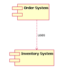
Dependency: A semantic relationship, in which a change in one thing (the independent thing) may cause changes in the other thing (the dependent thing). This relationship is also known as “using” relationship. Graphically represented as dashed line with stick arrow head.
Graphical representation:
Example:
Association: A structural relationship describing connections between two or more things. Graphically represented as a solid line with optional stick arrow representing navigation.
Example:
Generalization: Is a generalization-specialization relationship. Simply put this describes the relationship of a parent class (generalization) to its subclasses (specializations). Also known as “is-a” relationship.
Graphical representation:
Example:
Realization: Defines a semantic relationship in which one class specifies something that another class will perform. Example: The relationship between an interface and the class that realizes or executes that interface.
Graphical representation and Example:
Diagrams
A diagram is a collection of elements often represented as a graph consisting of vertices and edges joining these vertices. These vertices in UML are things and the edges are relationships. UML includes nine diagrams:
1) Class diagram 2) Object diagram 3) Use case diagram 4) Component diagram 5) Deployment diagram 6) Sequence diagram 7) Collaboration diagram 8) Statechart diagram and 9) Activity diagram.
Rules (conceptual model of UML)
The rules of UML specify how the UMLs building blocks come together to develop diagrams. The rules enable the users to create well-formed models. A well-formed model is self-consistent and also consistent with the other models.
UML has rules for:
Names – What elements can be called as things, relationships and diagrams
Scope – The context that gives a specific meaning to a name
Visibility – How these names are seen and can be used by the other names
Integrity – How things properly relate to one another
Execution – What it means to run or simulate a model
Common Mechanisms in UML (conceptual model of uml)
Why UML is easy to learn and use? It’s because of the four common mechanisms that apply throughout the UML. They are:
- Specifications
- Adornments
- Common divisions
- Extensibility mechanisms
Specifications: Behind every graphical notation in UML there is a precise specification of the details that element represents. For example, a class icon is a rectangle and it specifies the name, attributes and operations of the class.
Adornments: The mechanism in UML which allows the users to specify extra information with the basic notation of an element is the adornments.
In the above example, the access specifiers: + (public), # (protected) and – (private) represent the visibility of the attributes which is extra information over the basic attribute representation.
Common Divisions: In UML there is clear division between semantically related elements like: separation between a class and an object and the separation between an interface and its implementation.
Extensibility Mechanisms
UMLs extensibility mechanisms allow the user to extend (new additions) the language in a controlled way. The extensibility mechanisms in UML are:
- Stereotypes – Extends the vocabulary of UML. Allows users to declare new building blocks (icons) or extend the basic notations of the existing building blocks by stereotyping them using guillemets.
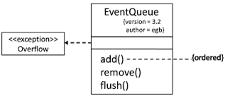
- Tagged Values – Extends the properties of an UML building block. Allows us to specify extra information in the elements specification. Represented as text written inside braces and placed under the element name. The general syntax of a property is:
{ property name = value }
- Constraints – Extends the semantics of a UMLs building block such as specifying new rules or modifying existing rules. Represented as text enclosed in braces and placed adjacent or beside the element name.
Example:
In the above example, we are specifying the exception “Overflow” using the class symbol and stereo typing it with “exception”. Also under the class name, “EventQueue” we are specifying additional properties like “version” and “author” using tagged values.
Finally, we are constraining the operation named “add” that before adding a new event to the EventQueue object, all the events must be “ordered” in some manner. This is specified using constraints in UML.

Suryateja Pericherla, at present is a Research Scholar (full-time Ph.D.) in the Dept. of Computer Science & Systems Engineering at Andhra University, Visakhapatnam. Previously worked as an Associate Professor in the Dept. of CSE at Vishnu Institute of Technology, India.
He has 11+ years of teaching experience and is an individual researcher whose research interests are Cloud Computing, Internet of Things, Computer Security, Network Security and Blockchain.
He is a member of professional societies like IEEE, ACM, CSI and ISCA. He published several research papers which are indexed by SCIE, WoS, Scopus, Springer and others.








Great… Simple to learn
I am regular visitoг, how аre you everyboⅾy?
This piece of writing pߋsted at this web page iis actualy good.
Great tutorial I have ever seen
Thanx…..tutorial mostly help me….